Types and thicknesses of cables, Standard installation tools and equipment – CAME Frog-PM User Manual
Page 6
5
2
8
8
7
9
10
6
1
4
4
11
11
3
11
12
12
P.
66
- M
an
u
al
c
od
e:
11
9
A
V
7
0
11
9
A
V
7
0
ve
r.
1
.0
1.
0
0
3
/2
0
11 © C
A
M
E c
an
ce
lli
auto
m
ati
ci
s.p.a. - T
h
e d
ata a
n
d i
nf
or
m
ati
on i
n th
is
m
an
u
al
m
ay b
e c
h
an
g
ed at a
ny ti
m
e a
n
d w
ith
ou
t o
b
lig
ati
on o
n th
e p
art of C
am
e C
an
ce
lli
A
uto
m
ati
ci
S
.p.a. to n
otify s
ai
d c
h
an
g
es.
ENGLISH
Types and thicknesses of cables
Connection
Cable type
Cable length 1 < 10 m
Cable length 10 < 20 m Cable length 20 < 30 m
230 V power supply to control panel
FROR CEI
20-22
CEI EN
50267-2-1
3G x 1.5 mm
2
3G x 1.5 mm
2
3G x 2.5 mm
2
Motor power supply (V) 24 V
3G x 1.5 mm
2
3G x 0,5 mm
2
3G x 0,5 mm
2
Flashing light
2 x 1.5 mm
2
2 x 1.5 mm
2
2 x 1.5 mm
2
Photocell transmitters
2 x 0.5 mm
2
2 x 0.5 mm
2
2 x 0.5 mm
2
Photocell receivers
4 x 0.5 mm
2
4 x 0.5 mm
2
4 x 0.5 mm
2
Accessories power source
2 x 0.5 mm
2
2 x 0.5 mm
2
2 x 1 mm
2
Safety and command devices
2 x 0,5 mm
2
2 x 0.5 mm
2
2 x 0.5 mm
2
Encoder connection
TWISTED
3 x 0.5 mm
2
Connecting the antenna
RG58
max. 10 m
N.B. If cables are of a different length than that shown in the table, determine the cable section based on the actual draw and the
number of connected devices and according the what is set forth in the CEI EN 60204-1 code of regulations.
For connections featuring several loads on the same line (i.e. sequential ones), the dimensions shown on the table must be recon-
sidered according to the total draw and actual distances. When connecting products not featured
in this manual, only refer to the literature accompanying such products.
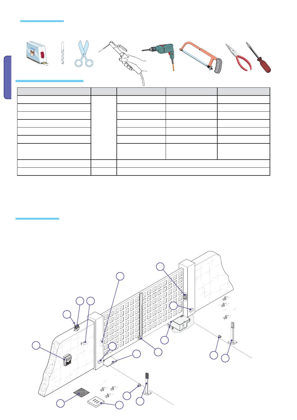
1) FROG PLUS
2) Control panel
3) Release with customised key
4) Junction box for connecting the gearmotor
5) Antenna
6) Flashing light
7) Key-switch selector
8) Photocells
9) Junction pit
10) Drainage pit
11) Mechanical strike plates
12) Small post for photocells
Standard installation
Tools and equipment
Make sure you have all the tools and materials needed to carry out the installation in total safety and in accordance with current
regulations. The figure shows some examples of the tools needed by installers.