Installation, Dimensions, Description of parts – CAME Frog-PM User Manual
Page 5: Preliminary checks
586
426
358
58
644
416
8
2
7
3
4
1
6
5
9
P.
55
-
M
an
u
al
c
od
e:
11
9
A
V
7
0
11
9
A
V
7
0
ve
r.
1
.0
1.
0
03
/2
0
11
© C
A
M
E c
an
ce
lli
auto
m
ati
ci
s.p.a. - T
h
e d
ata a
n
d i
nf
or
m
ati
on i
n th
is
m
an
u
al
m
ay b
e c
h
an
g
ed at a
ny ti
m
e a
n
d w
ith
ou
t o
b
lig
ati
on
o
n th
e p
art of C
am
e C
an
ce
lli
A
uto
m
ati
ci
S
.p.a. to n
otify s
ai
d c
h
an
g
es.
ENGLISH
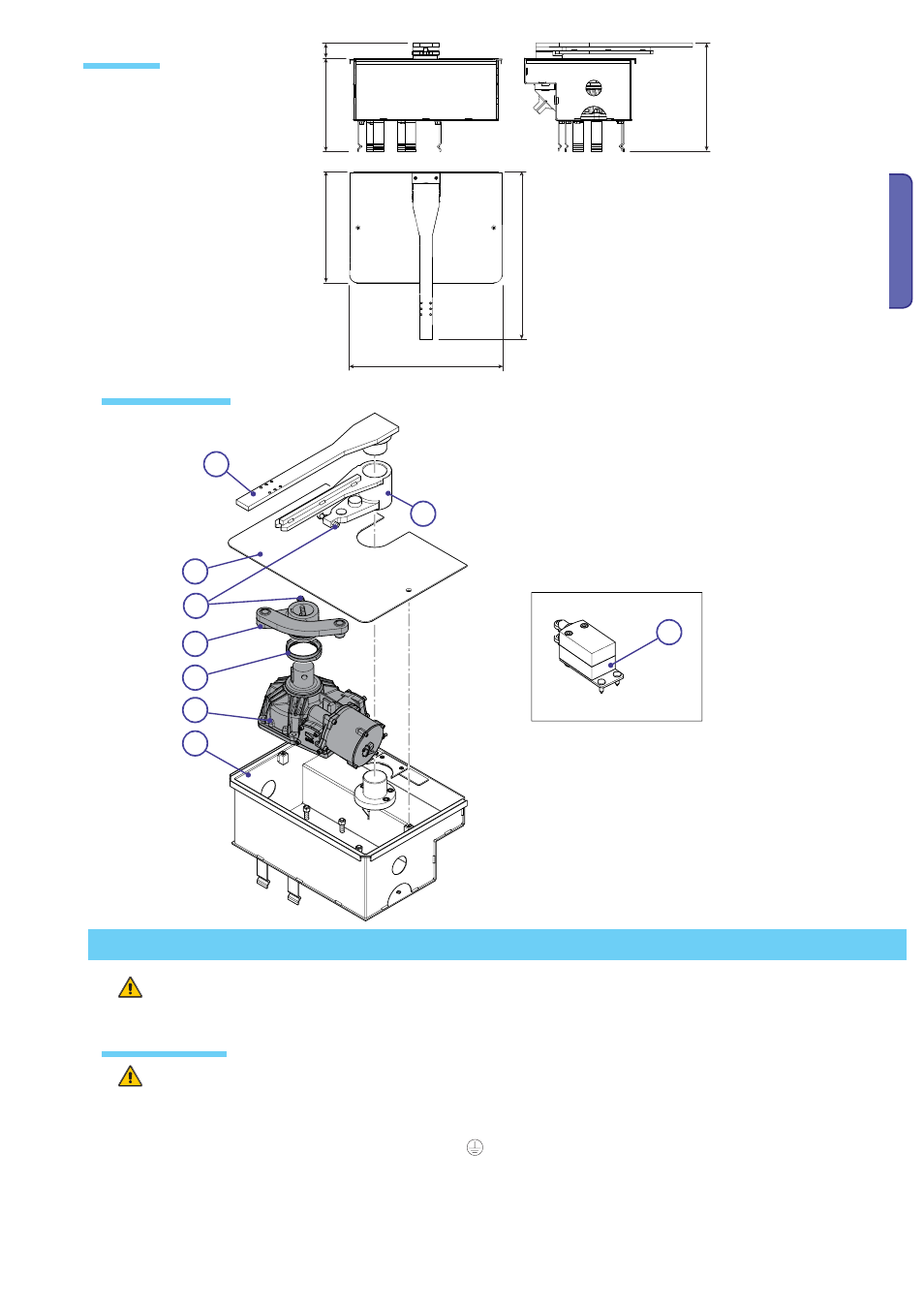
Dimensions
(mm)
Description of parts
1) Gearmotor
2) Lever
3) Cams
4) Gate bracket
5) Anchoring lever
6) Sink box
7) Box cover
8) Optional limit switch assembly
9) Limit switch adjusting screw
Installation
Preliminary checks
Before beginning to install, the following is necessary:
Set up a suitable omnipolar cut-off device, with distances greater than 3 mm between contacts, wit sectioned power source;
• Set up proper conduits and electric cable raceways, making sure these are protected from any mechanical damage;
• Set up a drainage tube to prevent stagnation of moisture that can lead to oxydation;
• Check that any protection circuit connections (ground),
inside the container, be properly insulated compared to the other
conductive parts.;
• Make sure the gate is sturdy enough, the hinges sound and that there is no friction among fixed and moving parts;
Make sure there are opening and closing strike plates.
Installation must be carried by skilled, qualified technicians in accordance with current regualtions.