Connecting to the control panel – CAME Frog-PM User Manual
Page 10
1
5
2
3
4
4
U V W X Y E
E
+
-
E
+
-
E3
P.
1
0
10
- M
an
u
al
c
od
e:
11
9
A
V
7
0
11
9
A
V
7
0
ve
r.
1
.0
1.
0
0
3
/2
0
11 © C
A
M
E c
an
ce
lli
auto
m
ati
ci
s.p.a. - T
h
e d
ata a
n
d i
nf
or
m
ati
on i
n th
is
m
an
u
al
m
ay b
e c
h
an
g
ed at a
ny ti
m
e a
n
d w
ith
ou
t o
b
lig
ati
on o
n th
e p
art of C
am
e C
an
ce
lli
A
uto
m
ati
ci
S
.p.a. to n
otify s
ai
d c
h
an
g
es.
ENGLISH
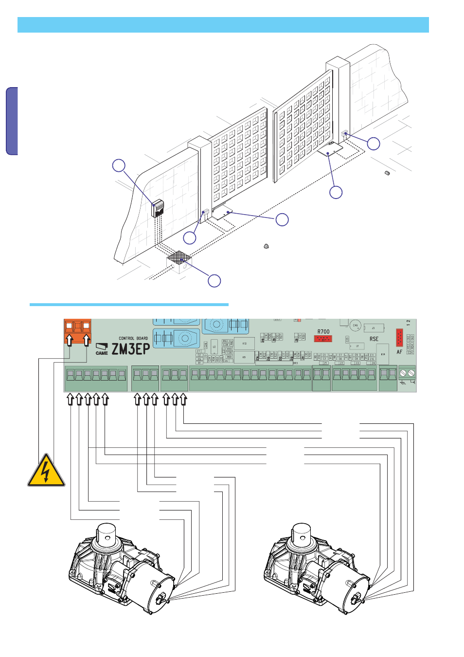
1) Control panel
2) Left gear motor
3) Right gearmotor
4) Junction box
5) Junction pit
Connecting the 230 V A.C. gearmotor with
opening delay
Connecting the 230 V A.C. gearmotor with
closing delay
230 V A.C.
Power supply
BLUE
BLACK
BROWN
BLUE
BROWN
BLACK
GREEN
BROWN
WHITE
Electrical connections of the gearmotors to the control panel
Connecting to the control panel
For electrical connections, check with the CAME control panel manual.
Check the control panel manual.
GREEN
BROWN
WHITE
- Frog-AE (10 pages)
- Frog-A 230v (10 pages)
- Frog-A 24v (12 pages)
- Myto ME (20 pages)
- Myto-C (8 pages)
- Ferni 230v (12 pages)
- Ferni 24v (12 pages)
- F1003 Stop Arm (2 pages)
- Amico (14 pages)
- Frog-PC (8 pages)
- Frog-J (16 pages)
- Stylo (20 pages)
- Krono (10 pages)
- Fast (24 pages)
- Axo (18 pages)
- Axo-P324 Kit (32 pages)
- Superfrog (12 pages)
- Bx-243 (22 pages)
- BX74 - BX78 (24 pages)
- BX-P (Pratico) (18 pages)
- BX10 (34 pages)
- BX-241 (16 pages)
- BX-246 (24 pages)
- Bk (22 pages)
- Ver (24 pages)
- FrogAE-P Kit (32 pages)
- FrogAE-S Kit (32 pages)
- Ati-P Kit (36 pages)
- Ati-S Kit (36 pages)
- FerniE-P24 Kit (36 pages)
- FerniE-S24 Kit (36 pages)
- Krono-P3 Kit (32 pages)
- Axo-P3 Kit (30 pages)
- BK-12P Kit (18 pages)
- Ver U4483-B Kit (22 pages)
- Gard6S Kit (24 pages)
- Gard4S Kit (24 pages)
- Gard2S Kit (12 pages)
- G4230ST Kit (16 pages)
- G424VST Kit (16 pages)
- G6230ST Kit (16 pages)
- G624VST Kit (16 pages)
- Flex U8600 Kit (8 pages)
- Tra08 (12 pages)