Drain outlet assembly installation – Hydrotech 12301_12302_12303 Series ADVANCED REVERSE OSMOSIS WATER TREATMENT SYSTEMS User Manual
Page 8
4
DRAIN OUTLET ASSEMBLY INSTALLATION
NOTE: State and local plumbing codes may prohibit use of saddle-tapping drain connections and may require use
of an air gap.
NOTE: Location and orientation of drain outlet assembly is vital to system performance.
SINK
SINK
VERTICAL
MOUNT
MAXIMUM DISPLACEMENT
FROM TOP CENTER-45°
HORIZONTAL
MOUNT
DISPOSAL
DRAIN LINE
FROM AIR GAP
( AIR GAP ONLY)
INSTALL HERE
DO NOT INSTALL HERE
Horizontal Drain Line:
Locate drain hole as close as possible to top of pipe
(between 45º and top) and as far as practical from
garbage disposal.
Vertical Drain Line:
Locate drain hole on a straight length of drainpipe next to
"P"/"S" trap between trap and sink.
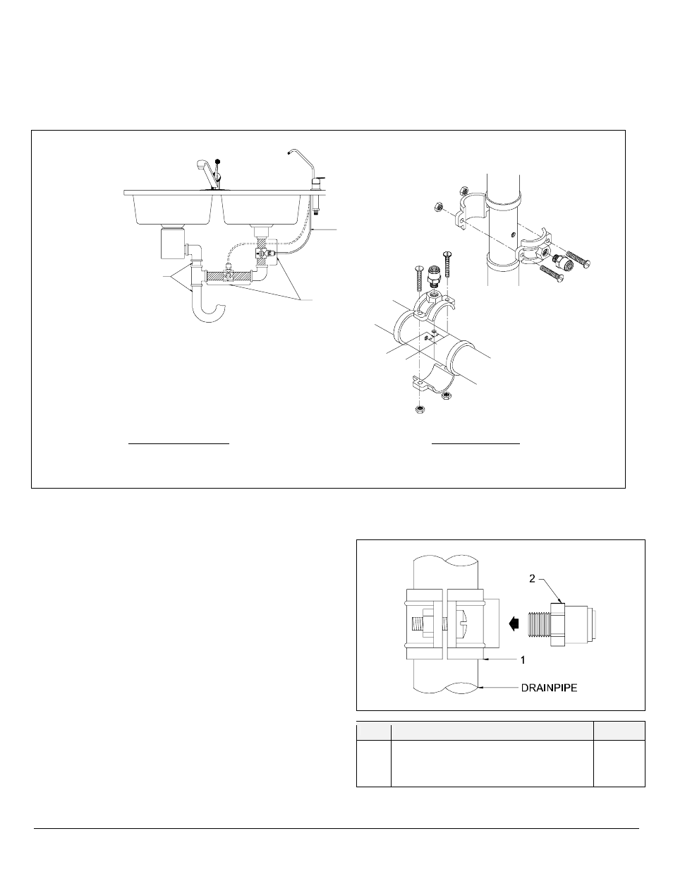
Figure 4:
Drain Hole Location and Installation, Air Gap Faucet
NOTE: See Page II, Figure 1.A. for connection to drain for Non-Air Gap Faucet.
1. Select a location for drain hole based on type of sink
and orientation of drain line (Figure 4).
NOTE: Item callouts refer to Figure 5 unless noted
otherwise.
2. Position drain outlet saddle (Item 1) on drainpipe.
Allow adequate space for drilling operation.
3. Tighten saddle bolts evenly on both sides. Avoid over-
tightening.
4. Using opening in drain saddle outlet as a guide, drill a
3/8" to 7/16" diameter hole in drainpipe. Clean any
debris out of drain saddle connection.
5. Install Male Connector (Item 2) fitting into drain saddle.
Use thread sealing tape (P/N 35700002) to seal
threads between male connector and drain saddle.
Item
Description
Part No.
1
2
Drain Saddle
Male Connector 1/4" X1/4” (Non-Air Gap)
Male Connector 3/8” x 1/4" (Air-Gap)
42000002
33503312
33503314
Figure 5:
Drain Outlet Assembly