Hydrotech 12301_12302_12303 Series ADVANCED REVERSE OSMOSIS WATER TREATMENT SYSTEMS User Manual
Page 12
8
POLYMER PRODUCT WATER FAUCET INSTALLATION AND SYSTEM CONNECTIONS
Install on flat surface at least 2 7/16" in diameter. Unused 1 1/4"- 1 7/16" opening is ideal.
New Faucet Installation
Refer to Faucet Site Preparation, Page 5.
Replacement Faucet Installation
Verify size of existing hole. If hole measures 1 7/16",
Faucet may be installed without changes. If hole measures
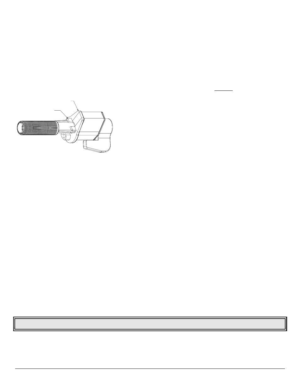
1 1/4", remove two locator tabs (Figure 8) prior to
installation by breaking them off at faucet base.
FAUCET BODY
TAB
Figure 8:
Faucet Locator Tabs and Air Gap.
1. Remove mounting nut and "U" bracket from faucet.
2. Install 3/8” blue tube into blue collet in faucet base.
3. CAUTION: Do not pinch, kink, pull, or otherwise
deform monitor cord.
Plain Front: Insert three tubes into mounting hole
and place faucet over hole.
4. CAUTION: Flow Restrictor (FLR) is installed inside
the 1/4” red tubing at the end connected to the
module. DO NOT TRIM THE END OF THE 1/4" FLR
RED TUBING (END WITH FLR LABEL)
CONNECTED TO MODULE (See Figure 10.A & 10.B).
Connect tubing between module and faucet:
a. Position module in desired location. Trim 3/8”
blue tubing to desired length.
b. Insert 3/8” blue tubing into 3/8” swivel elbow
located on rear of module.
c. Install ¼” union connector packaged with faucet to
¼” FLR red tubing from module.
d. Trim 1/4” red tubing coming from faucet to desired
length and connect to ¼” union connector.
5. Align faucet in mounting hole:
Plain Front: Align body with narrow face forward.
6. Install "U" bracket and mounting nut below sink.
Tighten mounting nut by hand so that faucet does
not move. Do not over tighten.
NOTE: Faucet is packaged for right-hand operation. For
left-hand operation, realign handle by completing Step 7.
NOTE: Item callouts in Step 7 refer to Page 9, Figure 9.
7. Align faucet knob for left-hand operation.
a. Rotate knob to rear of faucet (closed position).
b. Remove knob cover (Item 1) using a thin, flat tool
to pry cover from knob.
c. Remove knob attachment screw (Item 2) using a
Phillips-head
screwdriver.
d. Remove knob (Item 3) by pulling it (by hand)
straight up. Rotate handle counterclockwise 90º,
and re-install knob.
e. Install knob attachment screw. Tighten screw until
free movement (i.e., rocking) is eliminated.
f.
Snap knob cover into place.
8. Install spout into faucet body. Lubricate “O” ring with
FDA approved Silicone Lubricant. Align spout with
faucet outlet, gently push spout to bottom of outlet.
9. CAUTION: Red 3/8" tube connecting faucet to drain
connection must run vertically (or as closely as
possible) with no sharp bends or loops (See Page 4,
Figure
4).
Connect 3/8" red tubing to drain connection.
10. Product Water Storage Tank: Refer to Page 6 for
instructions. Specific instructions are shown for
Polymer and Metal Storage Tank Assemblies
CLEAN FAUCET SURFACE USING DISHWASHING DETERGENT ONLY. DO NOT USE ABRASIVES OR SOLVENTS.