American Dryer Corp. MD-170 User Manual
Page 68
64
e. Open main door. The dryer must stop and ALL output indicator lights on the back side of the micro-
processor (computer) board must go out.
f. Try to restart the dryer with the main door open.
g.The microprocessor (computer) board's L.E.D. display must read "DOOR."
h.Close the main door and restart the dryer.
i. Functional check of microprocessor (computer) board is complete.
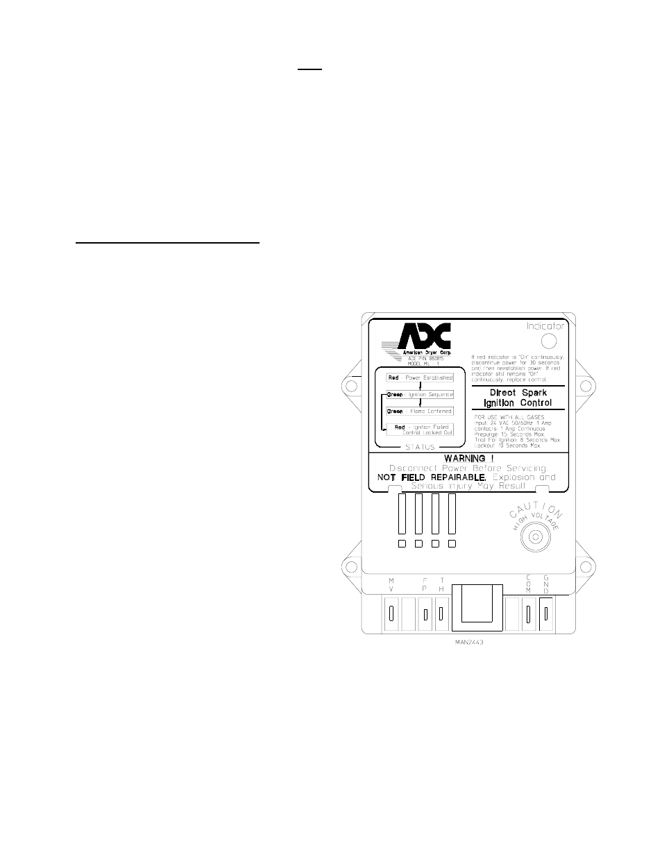
2. Direct Spark Ignition (DSI) System
a. Upon completing installation of the replacement
Direct Spark Ignition (DSI) module, reestablish power
to the dryer.
b. Start the drying cycle.
c. The ignition (DSI) module's L.E.D. indicator will light
"red" for up to approximately 1.5 seconds (pre-purge
time).
d. The module's indicator light will then turn "green." The
gas valve will be energized and the ignitor probe will
spark for approximately 8 seconds. The burner flame
should now be established.
e. With the burner flame on, remove the flame sensor wire
from the FS terminal of the DSI module.
f. The burner flame must shut off and the ignition
module must lock out with the DSI module's indicator
light "red".
g. Stop the drying cycle, with the flame sensor wire still
removed, restart the drying cycle.
h. The ignition module must proceed through the
pre-purge, with the indicator light "red", the ignition
trial time of approximately 8 seconds, with the
indicator light "green", and then proceed to lock out
with the indicator light "red".
i. Functional check of the Direct Spark Ignition (DSI) Module is complete.
1) Replace the flame sensor wire from the FS terminal to the DSI module.
Models manufactured with ADC module Part No. 880815