Burkert Type S030 User Manual
Page 7
24
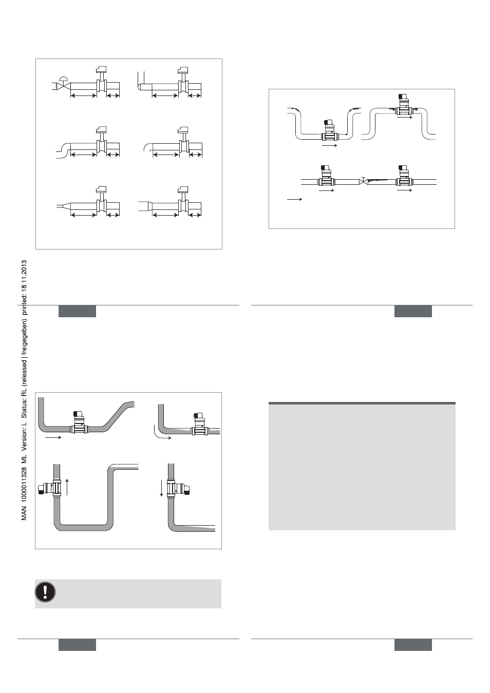
50 x DN 5 x DN
40 x DN 5 x DN
25 x DN 5 x DN
20 x DN 5 x DN
18 x DN 5 x DN
15 x DN 5 x DN
With control valve
Pipe with 2 elbows
at 90°
Pipe with 2 elbows at 90°
in 3 dimensions
Pipe with 1 elbow at 90°
or 1 T-piece
With pipe expansion
With pipe
reduction
Fig. 2: Upstream and downstream distances depending
on the design of the pipes.
→
Use a flow conditioner, if necessary, to obtain the best
accuracy.
English
25
→
Prevent the formation of air bubbles in the pipe (see
Fig. 3).
→
Ensure the pipe is always filled with liquid (see Fig. 4).
Correct
Correct
Incorrect
Incorrect
Direction of fluid flow
Fig. 3: Additional recommendations on installation
English
25
26
Correct
Incorrect
Correct
Incorrect
Fig. 4: Additional recommendations on installation
installing a fitting with weld ends
Follow the previously described general installation
recommendations.
English
27
note
the seal on the fitting with weld-end connections
may be damaged during welding.
→
Before welding the weld-ends, unscrew the 4 tight-
ening screws.
→
Remove the sensor holder.
→
Remove the seal.
→
Weld the weld-ends.
→
After welding, correctly replace the seal in the
groove.
→
Replace the sensor holder.
→
Tighten the 4 screws in an alternating pattern, app-
lying a nominal tightening torque of 1,5 Nm.
English
27