Installation safety instructions – Burkert Type S030 User Manual
Page 6
20
7. inSTAllATion
Safety instructions
danger
risk of injury due to high pressure in the installation.
• Stop the circulation of fluid, cut-off the pressure
and drain the pipe before loosening the process
connections.
risk of injury due to high fluid temperatures.
• Use safety gloves to handle the fitting.
• Stop the circulation of fluid and drain the pipe before
loosening the process connections.
risk of injury due to the nature of the fluid.
• Respect the prevailing regulations on accident pre-
vention and safety relating to the use of hazardous
products.
English
21
Warning
risk of injury due to non-conforming installation.
• Fluidic installation can only be carried out by qualified
and authorised personnel with the appropriate tools.
• Observe the installation instructions for the measuring
device inserted into the fitting.
risk of injury due to an uncontrolled restart.
• Ensure that the restart of the installation is controlled
after any interventions on it.
Warning
risk of injury if the fluid pressure/ temperature
dependency is not respected.
• Take into account the fluid pressure/ temperature
dependency according to the materials from which the
fitting is made and to the measuring device used (see
the relevant user manual).
• Comply with the Pressure Directive 97/23/EC.
→
Select an appropriate fitting regarding to the flow
velocity and the flow rate of the fluid in the piping, see
the following charts:
English
21
22
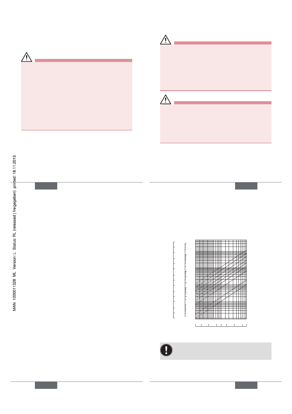
The graph is used to determine the DN of the pipe and the
fitting appropriate to the application, according to the fluid
velocity and the flow rate.
Selection example:
• Specification: if the nominal flow is 10 m
3
/h, the dimen-
sioning of the optimal flow rate must be contained in 2
to 3 m/s
• Answer: on the chart, the intersection of flow rate and
flow velocity gives the appropriate diameter, DN40 or
DN50 for fittings with *.
* For fittings:
• with external threads according to SMS 1145,
• with weld ends according to SMS 3008, BS 4825 /
ASME BPE or DIN 11850 Rg2
• Clamp according to SMS 3017 / ISO 2852 or
BS 4825 / ASME BPE or DIN 32676
English
23
l/min
5000
1000
100
3
2
1
20
10
0.5
5
0.3
0.2
500
50
0.01
0.02
0.05
0.1
0.2
0.5
1
2
5
10
20
50
100
200
500
m3/h
m/s
fps
gpm
2000
1000
500
200
20
10
0.5
0.2
0.1
0.05
100
50
0.1 0.2
0.5 1
2 3 5
10
0.3 0.5 1
2 3 5
10 20 30
5
2
1
200
2000
DN65
DN50 (DN65)*
DN40 (DN50)*
DN32 (DN40)*
DN25 (DN32)*
DN20 (DN25)*
DN15 (DN15 or
DN20)*
DN08
DN06
flow rate
Fluid velocity
To reduce the water hammer effects, install a
special device such as an 80 bar calibrated
exhaust valve within the circuit.
→
Install the fitting on the pipe to comply with the
upstream and downstream distances defined by
standard EN ISO 5167-1 (see Fig. 2).
English
23