English – Burkert Type 8012 User Manual
Page 34
34
Installationandwiring
Type 8012
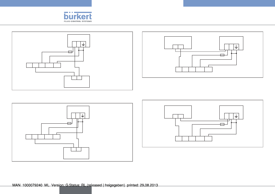
12-36 VDC
+
-
(*)
YE GY BN WH GN
Power supply
Load
grey
brown
white
green
Fig. 14 : NPN wiring (default) of the pulse output of a version with
cable gland
12-36 VDC
+
-
(*)
YE GY BN WH GN
Power supply
Load
brown
grey
white
green
Fig. 15 : PNP wiring of the pulse output of a version with cable
gland
12-36 VDC
+
-
(*)
YE GY BN WH GN
+
-
4-20mA input
at external
device
Power
supply
yellow
brown
white
green
Fig. 16 : Wiring the current output in sinking mode (by default) on a
version with cable gland
(*) Functional earth; If a direct earth connection is not possible, fit a 100 nF /
50 V capacitor between the negative power supply terminal and the earth.
12-36 VDC
+
-
(*)
YE GY BN WH GN
+
-
brown
white
4-20mA input
at external
device
Power
supply
yellow
green
Fig. 17 : Wiring the current output in sourcing mode on a version
with cable gland
(*) Functional earth; If a direct earth connection is not possible, fit a 100 nF /
50 V capacitor between the negative power supply terminal and the earth.
English