Burkert Type 1078-2 User Manual
Page 5
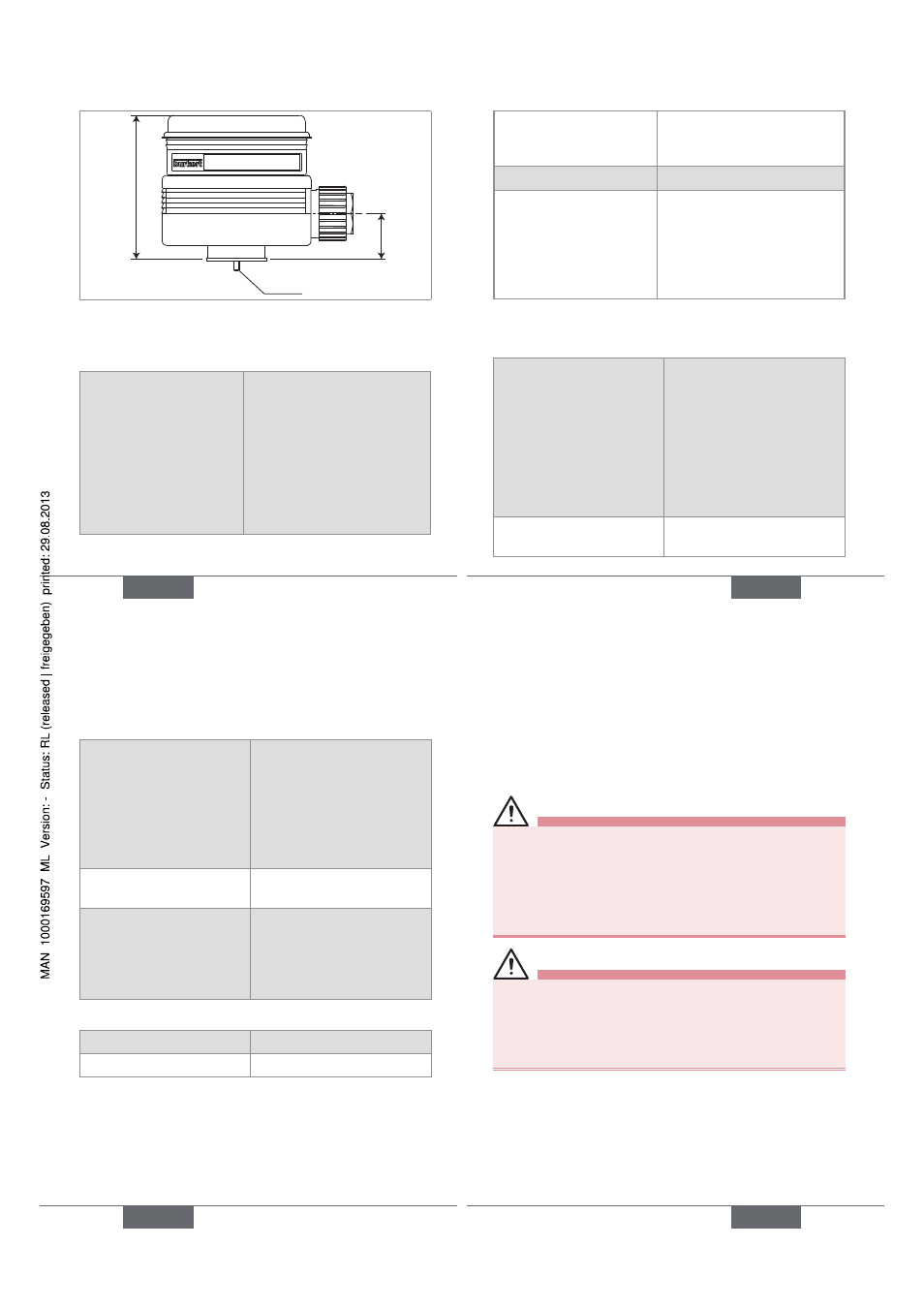
16
53,5
21
M3x55
Fig. 4: Dimensions [mm] of the 1078-2 combined with
the 1077-2
6.2.2. General
features
Time range (1078-1)
(mechanical adjustment
using the 6 switches N°
1, 2, 3, 6, 7 and 8)
• 0,5 to 10 s (default setting)
• 1,5 to 30 s
• 5 to 100 s
• 0,5 to 10 min.
• 1,5 to 30 min.
• 5 to 100 min.
• 12 to 240 min.
• 0,5 to 10 h
English
17
Time range (1078-2)
(digital adjustment through
module 1077-2)
0,2 s to 9999 h, continuous
Tolerance (1078-2)
1 %
Resolution (1078-2)
• up to 199 s
• up to 199 min.
• up to 99 h
• up to 9999 h
• 10 ms
• 1 s
• 1 min.
• 1 h
6.2.3. Electrical
data
Table 1:
Electrical data of the 1078
Power supply
• 1078-1
• 1078-2
Tolerance 10 %
• 12-24 V DC, max. 2 A
or 24-48 V AC/DC, max
1,5 A or 110/230 V AC,
max 0,5 A
• 12-24 V DC, max. 2 A
or 24-48 V AC/DC, max
1,5 A
Protection against polarity
reversal
No, for devices energized
with a direct voltage
English
17
18
Power supplied to the
solenoid valve
• Version 12-24 V DC
• Version 24-48 V AC/DC
• Version 110/230 V AC
• 12-24 V DC, max. 2 A
• 24-48 V DC, max. 1,5 A
• 110/230 V DC, max.
0,5 A
Clearance and leakage
path
Acc. to VDE 0100
Electrical connection
• Cable diameter
• Cross section of the
wires
Through PG9 cable gland
• 6 to 7 mm
• max. 1,5 mm
2
Table 2:
Electrical data of the 1077-2
Supply voltage
Energized by the 1078-2
Power consumed
5 mW
English
19
7.
INSTALLATION AND WIRING
7.1. Safety information
DANGER
Risk of injury due to electrical voltage.
• Before starting work, make sure that you switch off the
supply voltage and secure it to prevent restarting.
• Do not unscrew the cover of a powered device.
• Observe all applicable accident protection and safety
guidelines for electrical equipment.
WARNING
Risk of injury due to nonconforming installation.
• The electrical installation can only be carried out by
qualified and skilled staff with the appropriate tools.
• Install appropriate safety devices (correctly rated fuse
and/or circuit-breaker).
English
19