Installation – Burkert Type 0212-B User Manual
Page 4
english
12
pneumatic data
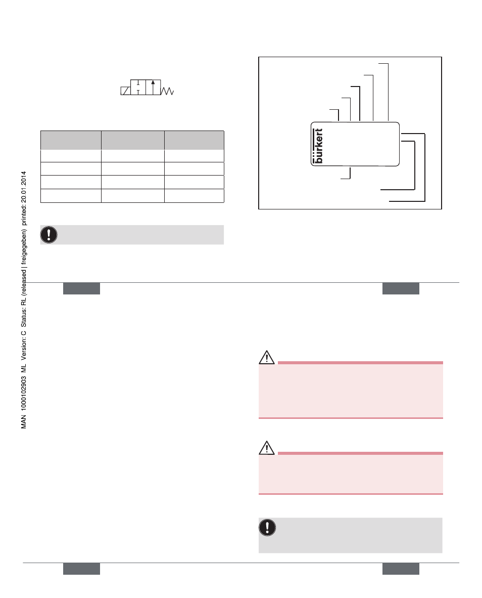
Operating principle
2/2-way valve, direct action
B (NO)
A
P
Pressure range
Nominal width
Pressure range
for AC [bar]
Pressure range
for DC [bar]
1,0
0-12
0-12
2,0
0-12
0-12
2,5
0-12
0-10
3,0
0-10
0-6
Line connections Bürkert flange 001-01-06 (32×32)
Note the information specified on the rating plate for
voltage, type of current, and pressure.
english
13
Rating plate (example)
Made in Germany
00450000
W14UN
CE
0212 B 3,0 FKM MS
FLNSCH PN0-6bar
24V DC 8W
Ident. no.
Voltage/Frequency/Output
Nominal connection pressure
Type
Operating principle
Nominal width
Sealant
Housing material
english
14
electrical data
Operating voltage
12 V DC
24 V DC
24 V 50 - 60 Hz
110 V 50 - 60 Hz
120 V 60 Hz
230 V 50 - 60 Hz
240 V 50 - 60 Hz
Voltage tolerance
± 10 %
Coil power consumption AC
21 VA (closed),
12 VA / 8 W (operation)
DC
8 W
Nominal operating mode in continuous operation ED 100%,
with block installation ED 60%
english
15
insTallaTiOn
safety instructions
Warning!
Risk of injury when installing the valve.
This work may be carried out by authorised technicians
•
only and with the appropriate tools!
After an interruption in the power supply or pneumatic
•
supply, ensure that the process is restarted in a defined
or controlled manner!
Fluid installation
Danger!
Danger - high pressure!
Danger of severe injuries from reaching into the system.
Before loosening the lines and valves, turn off the pres-
•
sure and vent the lines.
Installation position: any position, preferably with the drive
facing up.
To ensure a longer service life for the device, we
recommend an installation position with the magnet
system pointing up, since this will prevent falling
materials from getting into the core area.
Type 0212B