Analog i/o pin connections – Brooks Instrument SLA5810/20 User Manual
Page 19
2-5
Section 2 Installation
Models SLA5810 and SLA5820
Installation and Operation Manual
X-PR-SLA5800-PC-eng
Part Number: 541B091AAG
July, 2010
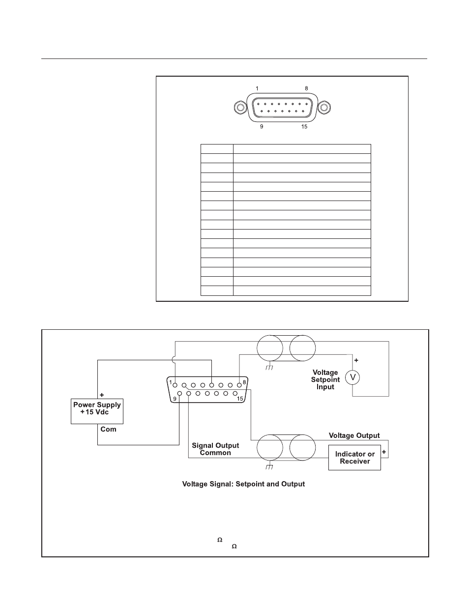
Figure 2-2 Common Electrical Hookups Voltage I/O Version
Figure 2-1 D-Connector Shielded Cable Hookup Diagram - Analog I/O Options.
Analog I/O Pin Connections:
PIN #
FUNCTION
1
Setpoint Command Input (-)
2
Signal, 0(1)-5 volt, Output (+)
3
Not Connected
4
5
Power Supply, +15 Vdc or +24 Vdc (+)
6
7
8
9
Power Supply, Common (-)
10
Signal, Common, Output, (-)
11
Reference, +5 Vdc, Output, (+)
12
Valve Override, Input
13
Calibration Select, Input
14
Chassis Ground
15
External Sensor, Input
Signal, 0(4)-20 mA, Output (+)
Not Connected
Setpoint, 0(4)-20 mA, Input (+)
Setpoint, 0(1)-5 volt, Input (+)
Notes:
1. The commons for the setpoint and signal output are not isolated from power supply common.
2. The cable shields should connect to chassis ground at one end only (Pressure Controller only).
3. Input impedence of setpoint input is >990K
. Maximum allowable input signal is 20 Vdc.
4. Minimum load resistance of voltage output is 2K
.
or +24 Vdc