Identification, Installation, Mechanical drawing – eLine Technology PRO3 Effio E User Manual
Page 3: Installation information, Accessories dc iris, General overview)
3
4
NOTE: Make sure you don’t have any missing parts before you make the installation.
Incorrect installation could void the warranty if instructions are not followed correctly.
Please call technical for assistance if you are unsure about any procedures.
Identification
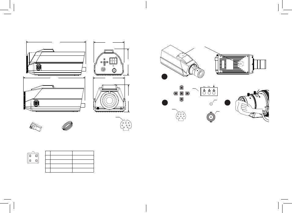
Mechanical Drawing
Installation
Installation information
(General overview)
Accessories
DC IRIS
1
Box Camera require only a few steps for installation:
The position (1) shows the 1/4 20UNC bracket fitting location one top or rear
this allows you to install in different fitting locations as your bracket dictates.
2
(1) Connect your video camera to the BNC connector here.
(3) Connect the 12v DC Power source or AC 24V (optional model) to terminals:
a. positive (+) wire for DC, any supply wire for AC.
b: negative (-) wire for DC, other supply wire for AC.
3
With all good installations clean lens just to make sure when installed you have not
accidentally put a smear or mark which might effect the picture.
(a) Auto Iris connector
(b) Adapter-ring
Pin
1
2
3
4
Video iris lens
Power
Null
Video signal
Ground
Damp-
Damp+
Drive+
Drive-
Figure: Auto iris
connector Jack
DC iris lens
1
2
3
4
VIDEO
LED
+
-
AC24V/DC12V
1
4
2
3
I/O Connector
1
2
3
4
5
6
7
8
Rear I / O Interface.
1) Black RS-485+ (Effio-P & Effio-S)
2) Brown RS-485- (Effio-P & Effio-S)
3) Orange NC
4) Blue D / N_OUT night status signal
output (color: H; black & white: L)
5) Green ALARM_OUT alarm output
(motion: L; no motion: H)
6) Yellow GND to
7) White EXT_IN external trigger input
(L / NC: Day mode; H: Night mode)
8) Red POWER 3.3V DC
Note: H = 3.3V; L = GND
1
3
2
VIDEO OUT
74 mm
3"
64 mm
2 1/2"
145 mm
5 3/4"
~+
24VAC / 12VDC
-~
I/O
74 mm
3"
63 mm
2 1/2"
145 mm
5 3/4"
1