Overview description – ADT Security Services ADT-APS-6R User Manual
Page 6
1. Overview
Description
6
ADT-APS-6R Instruction PN 50935:B 7/21/00
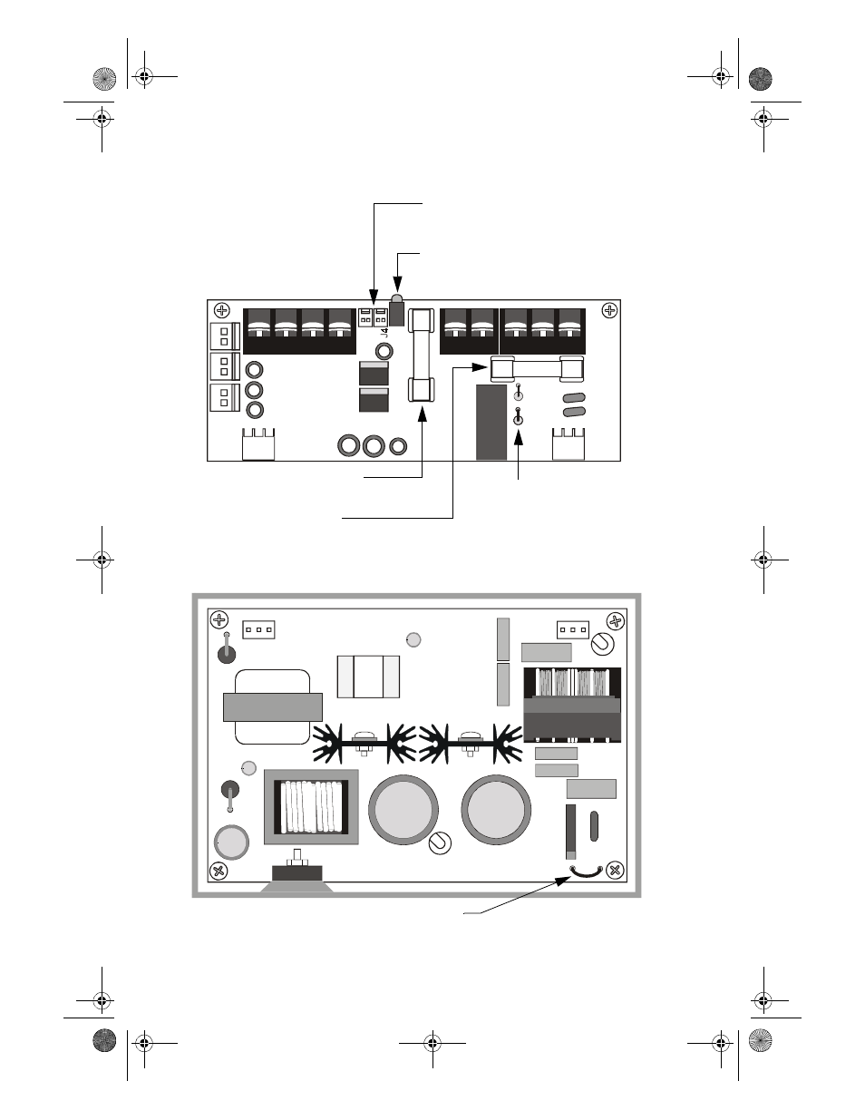
The figures below identify the features of the ADT-APS-6R power
supply:
Figure 2 ADT-APS-6R Control Board
Figure 3 ADT-APS-6R Main Board
J2
J9
J3
J1
TB
2
JP
3
JP
2
Fuse F1 for AC protection
(4A, 3AG, slow blow)
Three 24 VDC output circuits
Two (2) power-limited
One (1) non power-limited
Trouble In (J4) - Trouble Out (J3)
“P” style connectors for internal cabinet
connections
LED Status Indicators:
Green LED – Indicates AC power on
Yellow LED – Indicates loss of AC or battery
Fuse F2 for battery protection
(10A, 3AG, slow blow)
Jumpers JP2 and JP3 for
selecting 8-hour or 16-hour
delay for AC loss reporting
(default is immediate)
A
P
S
-6R
s
ide
b
rd.
c
d
r
JP
1
Jumper JP1 for selecting AC input voltage
(120 VAC default)
A
P
S
-6R
bo
a
rd.
c
d
r
ADTAPS-6R__INSTENGLB0.fm Page 6 Tuesday, November 21, 2000 11:30 AM