Datamax-O'Neil Performance series Wireless User Manual
Page 8
Wireless Installation Instructions | 1
5
Wireless Installation Guide
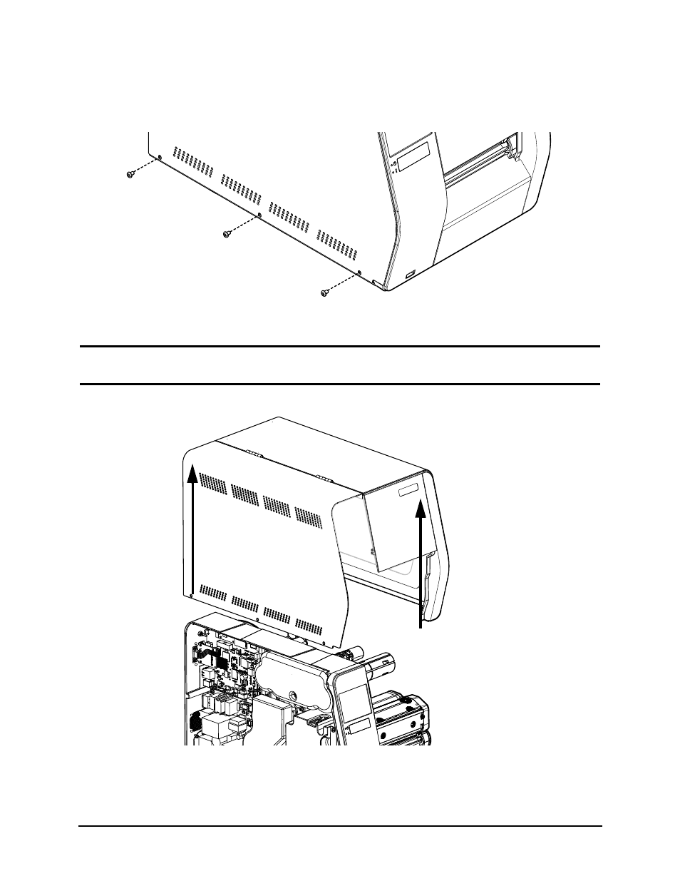
6. Loosen and remove the three (3) 2.5mm hex head screws securing the right side
cover to the printer chassis.
Figure: 1 - 5 Right Side Screws
7. Lift and remove the cover assembly from the printer chassis.
Caution:
Exercise caution when removing the cover set assembly and secure it in a safe
position where it will not be damaged.
Figure: 1 - 6 Lift Cover Assembly
8. Insert the wireless module sub-assembly into its connection point on the main PCB
assembly.
See also other documents in the category Datamax-O'Neil Printers:
- MF8I 270 User Guide (20 pages)
- MF8I Installation Guide (18 pages)
- MF8I Truck Mount Cable (2 pages)
- MF8I Locking Mounting Bracket (2 pages)
- MF8I Economy Mounting Bracket (2 pages)
- MF8I AN-15 (Line Printer and Easy Print Modes) (7 pages)
- MF8I AN-16 (Single Byte Character Set Font File Format) (8 pages)
- MF8I Quick Reference Programming Guide (72 pages)
- MF8I Configuration Program Installation (1 page)
- MF8I Bluetooth Management Component for Wavelink Avalanche (10 pages)
- A-Class Mark II Operator’s Manual (160 pages)
- A-Class Mark II Installation (2 pages)
- A-Class Mark II DMXrfNetIII (16 pages)
- A-Class Mark II DMXrfNetII (16 pages)
- A-Class Mark II RFID Quick Start Guide (6 pages)
- A-Class Mark II Programmer’s Manual (334 pages)
- ANDES 3 User Guide (32 pages)
- ANDES 3 Quick Start Guide (2 pages)
- ANDES Series Programmer’s Manual (67 pages)
- APEX 2 User Guide (28 pages)
- APEX 2 Quick Start Guide (2 pages)
- APEX 3 User Guide (27 pages)
- APEX 3 Quick Start Guide (2 pages)
- APEX 4 User Guide (30 pages)
- APEX 4 Quick Start Guide (2 pages)
- E-Class Mark III Operator’s Manual (90 pages)
- E-Class Mark III 4xxxxxxx Operator’s Manual (58 pages)
- E-Class Mark III 3xxxxxxx Operator’s Manual (58 pages)
- E-Class Mark III Paper Menu (7 pages)
- E-Class Mark III DPL Programmer’s Manual (296 pages)
- E-Class Mark III Printhead Bracket and Screw Upgrade (11 pages)
- H-Class Operator’s Manual (180 pages)
- Static brush (2 pages)
- H-Class Media Retainer (1 page)
- H-Class Thermal Transfer Option (12 pages)
- H-Class RFID Option (8 pages)
- H-Class Powered Internal Rewind Option (10 pages)
- H-Class Internal Rewind Option (6 pages)
- H-Class Present Sensor Option (8 pages)
- H-Class Peel & Present Option (8 pages)
- H-Class Linear Scanner Option (26 pages)
- H-Class HD Peel & Present Option (10 pages)
- H-Class HD Cutter Option (12 pages)
- H-Class GPIO Option (14 pages)
- H-Class Cutter Option (10 pages)