Datamax-O'Neil APEX 2 User Guide User Manual
Page 16
12
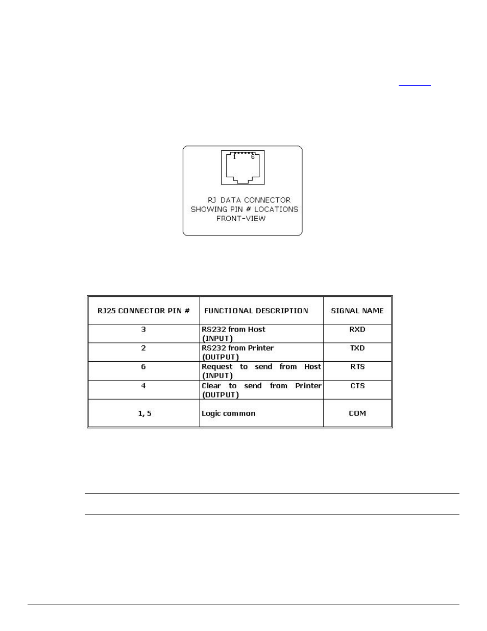
3.3 Serial Communication
The RS232C Interface signals for the APEX 2 Series printers are terminated on a 6 PIN RJ
type data connector located on the side of the printer.
Six connections are provided from the Serial Interface to the host computer.
Table 3
,
below, lists the Serial Interface signals and pin outs on the RJ connector. The connector
pin locations are shown in Figure 11.
A minimum of two pin connections are required for operation, RXD – pin 3 and Common –
pin 1.
FIGURE 11: RJ DATA CONNECTOR
Table 3 – APEX 2 Serial RS232C Interface signals
Dip Switch #1 and #2 must be in the
interface
Note: The communication parameters: Baud rate, Data Bit and Parity settings must match those of
the host device. Dip switch #1 must be in the OFF position.
- MF8I 270 User Guide (20 pages)
- MF8I Installation Guide (18 pages)
- MF8I Truck Mount Cable (2 pages)
- MF8I Locking Mounting Bracket (2 pages)
- MF8I Economy Mounting Bracket (2 pages)
- MF8I AN-15 (Line Printer and Easy Print Modes) (7 pages)
- MF8I AN-16 (Single Byte Character Set Font File Format) (8 pages)
- MF8I Quick Reference Programming Guide (72 pages)
- MF8I Configuration Program Installation (1 page)
- MF8I Bluetooth Management Component for Wavelink Avalanche (10 pages)
- A-Class Mark II Operator’s Manual (160 pages)
- A-Class Mark II Installation (2 pages)
- A-Class Mark II DMXrfNetIII (16 pages)
- A-Class Mark II DMXrfNetII (16 pages)
- A-Class Mark II RFID Quick Start Guide (6 pages)
- A-Class Mark II Programmer’s Manual (334 pages)
- ANDES 3 User Guide (32 pages)
- ANDES 3 Quick Start Guide (2 pages)
- ANDES Series Programmer’s Manual (67 pages)
- APEX 2 Quick Start Guide (2 pages)
- APEX 3 User Guide (27 pages)
- APEX 3 Quick Start Guide (2 pages)
- APEX 4 User Guide (30 pages)
- APEX 4 Quick Start Guide (2 pages)
- E-Class Mark III Operator’s Manual (90 pages)
- E-Class Mark III 4xxxxxxx Operator’s Manual (58 pages)
- E-Class Mark III 3xxxxxxx Operator’s Manual (58 pages)
- E-Class Mark III Paper Menu (7 pages)
- E-Class Mark III DPL Programmer’s Manual (296 pages)
- E-Class Mark III Printhead Bracket and Screw Upgrade (11 pages)
- H-Class Operator’s Manual (180 pages)
- Static brush (2 pages)
- H-Class Media Retainer (1 page)
- H-Class Thermal Transfer Option (12 pages)
- H-Class RFID Option (8 pages)
- H-Class Powered Internal Rewind Option (10 pages)
- H-Class Internal Rewind Option (6 pages)
- H-Class Present Sensor Option (8 pages)
- H-Class Peel & Present Option (8 pages)
- H-Class Linear Scanner Option (26 pages)
- H-Class HD Peel & Present Option (10 pages)
- H-Class HD Cutter Option (12 pages)
- H-Class GPIO Option (14 pages)
- H-Class Cutter Option (10 pages)