Smart matrix - ref. smx200 rear panel description – Analog Way Smart MatriX User Manual
Page 3
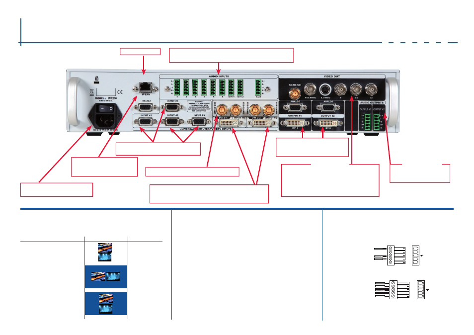
Smart MatriX - Ref. SMX200
Rear Panel Description
VIDEO OuT
RS-232 communication port
on a DB9 female connector or
TCP/IP on RJ45 connector
Power supply: IEC/EN/uL/CSA
60950-1, internal, autoswitchable
universal Analog Computer/TV/HDTV
inputs #1 to #4
SD-SDI/HD-SDI inputs #1 to #4: female BNC
Connectors:
1x BNC-F: SD/HD-SDI (with audio embedded)
3x BNC-F: Y_Cb_Cr
1x Mini Din 4: S. Video
1x BNC-F: Composite video PAL/NTSC
IP-LAN connector
Balanced or unbalanced mono/stereo inputs (all pin MCO
male connectors). DVI #1 & #2 and AuX.
A U D I O C O N N E C T I O N S
H O M E M E N U
The Home Menu is the system’s top level menu, from which all others menus
can be accessed. To access a menu, press the [MENu] button. To navigate
in the Home Menu, please use the knob. To confirm, please use the [ENTER]
button. You can also return to the Home Menu by pressing the [EXIT] button.
-
INPUT:
configure the 12 individual input types and resolutions.
-
OUTPUT 1:
in Matrix mode, select to set the output types and resolutions
of Output #1.
-
OUTPUT 2:
in Matrix mode, select to set the output types and resolutions
of Output #2.
-
VIDEO OUT:
configure Video output card settings.
-
PRESET:
store and use presets.
-
AUDIO:
access all audio input and output parameters.
-
CONTROL:
access device software information, LAN settings, reset factory
settings, amongst other user oriented functions (see next page).
V I D E O O U T
In Matrix Mode, the menu “Connection Mode” appears. It allows you to choose
recording Output
#
1 or Output
#
2.
AuDIO OuTPuT
Main audio Outputs #1 to #2 for
Matrix Mode (Balanced)
A U D I O C O N N E C T I O N S
L DVI 1
R DVI 1
L DVI 2
R DVI 2
UNBALANCED
LEFT DIV 1
RIGHT DIV 1
LEFT DIV 2
RIGHT DIV 2
GROUND
4
L+
L-
R+
R-
BALANCED
L+
R+
L-
R-
GROUND(S)
MCO male connectors
Inputs #1 to #6: Balanced & unbalanced connection
Inputs DVI #1 to DVI #2: Balanced & unbalanced connection
Input AuX: Balanced & unbalanced connection
Outputs #1 to #2: Balanced & unbalanced connection
DVI connectors: DVI-D inputs #1 and #2 on the DVI-I
digital pins, and universal Analog inputs #5 & #6 on
the DVI-I analog pins. use the included break-in cable.
Outputs #1 & #2: female HD15,
DVI-I (simultaneous analog and
digital outputs)
Display Mode
Presentation
Availability
YES
YES
OUT #1
OUT #1
OUT #1
OUT #2
OUT #2
OUT #2
Output #1
Output #2
Output #1 & #2 side by side
Output #1 & #2 Top and Bottom
Menu→ Video Out → Connection
→ Output Titled Horizontally
Menu→ Video Out → Connection
→ Output Titled Vertically
Matrix Mode only
Matrix Mode only