Installation, Remote control connection, Rf coax and icc-net operation – Contemporary Research ICE-HE User Manual
Page 7: Ac power and net led operation, I/o port connection
Contemporary Research
7
ICE-HE Ethernet Head End
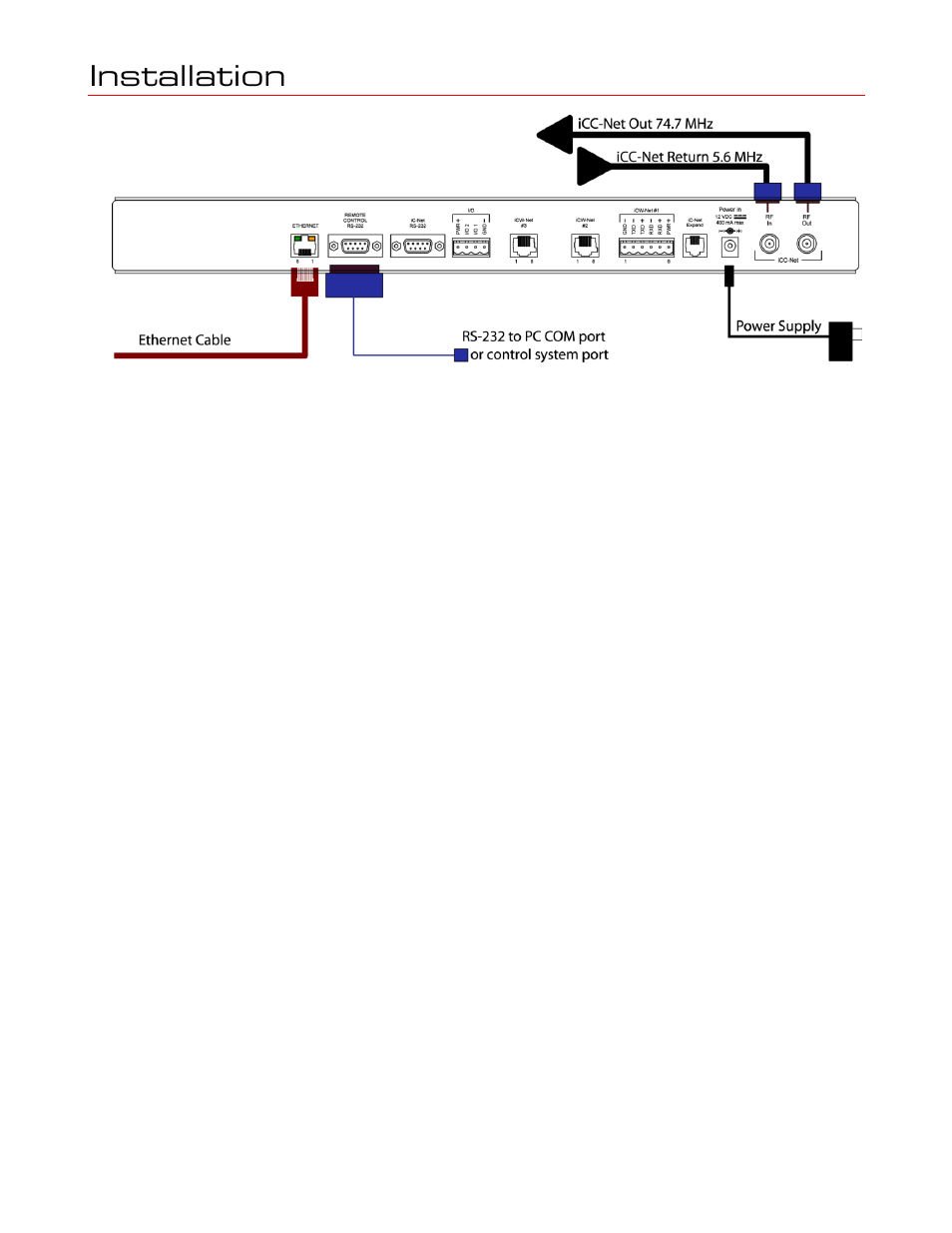
Remote Control Connection
1. Attach appropriate RS-232 cable to Remote Control RS-232 port. See page 4 for RS-232 cable
wiring diagram.
2. Set desired baud rate on front-panel DIP switch. Default setting is 19.2K baud – see page 4 for
DIP switch setting information.
3. Alternatively, connect via Ethernet, setup instructions on the next page.
RF Coax and iCC-Net Operation
1. Connect an RF coax feed from RF Out to the system‘s RF combiner, mixing the iCC-Net Out signal
with the other CATV channels. The iCC-Net Out channel operates at 74.7 MHz, in between cable
channels 4 and 5.
2. In most applications, the installer will connect the included 10 dB attenuator in between, trimming
the He‘s standard 55 dB output to 45 dB.
3. Using an RF signal level meter, use the front panel RF Out adjustment counterclockwise to match
the RF Out signal to the other CATV sources. Limit RF Out adjustment to -10 dB, using
attenuators to achieve a lower signal strength.
4. Add a Sub-CATV Diplexer after the CATV amplifier.
5.
Connect the Sub-Channel output of the Diplexer to the HE RF In connection
.
AC Power and Net LED operation
1. Insert DC power supply plug into the Power In jack.
2. Plug power adaptor into AC wall outlet, the front-panel LEDs should turn on momentarily.
3. If iC-Net communication is functioning, the Net LED will flash once per second, or twice per
second (the double-flash, indicating a difference between present and expected device, would be
typical in the initial phase of the installation.)
4. Using a terminal emulator, send an AR command (p9) a few times to measure the level of
background RF compared to the current Sensitivity setting (DIP switch 1, p4).
5. Set one iC-Net controller to constantly transmit using iC ToolKit. Send the AR command again the
measure the level at Constant Transmit.
6. The Sensitivity level should be set in-between the background RF and constant transmit levels.
I/O Port Connection
1. A simple contact closure can be wired to I/O 1 or 2, a press or release can trigger events in the
PC or control system software.
2. In other applications, the I/O ports can act as closure outputs, activating an external power relay,
2x1 video switcher or other device.
3. You‘ll have to choose application – the ports act as either an output or input, not both. See
Control Connections on page 5 for wiring and rating information.