Control connections, Icc-net connections – Contemporary Research ICE-HE User Manual
Page 5
Contemporary Research
5
ICE-HE Ethernet Head End
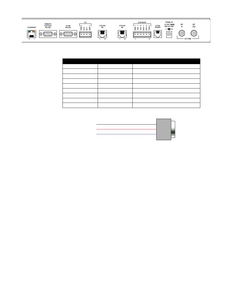
5 GND
2 RXD
3 TXD
RXD 2
GND 5
TXD 3
9-pin D-sub
female
RS-232
Control Port
Control Connections
Ethernet:
10/100baseT RJ-45 jack, RCX/TX LEDs indicate Ethernet data send and receive
Left LED
Right LED
Indication
Off
Off
No link
Off
Solid Amber
100BASE-T Half Duplex link
Off
Blinking Amber
100BASE-T Half Duplex link, activity
Off
Solid Green
100BASE-T Full Duplex link
Off
Blinking Green
100BASE-T Full Duplex link, activity
Solid Amber
Off
10BASE-T Half Duplex link
Blinking Amber
Off
10BASE-T Half Duplex link, activity
Solid Green
Off
10BASE-T Full Duplex link
Blinking Green
Off
10BASE-T Full Duplex link, activity
Control RS-232:
DB9 female, RS-232 data link to control system or PC
iC-Net RS-232:
DB9 female, RS-232 data link to send iCW-Net over fiber or codec
I/O 1 & 2:
4-pin captive screw terminal for Input/Outputs 1 and 2
2 switch closures or inputs, max 50 mA, 24 VDC, switch to GND
1 – +12 VDC
2 – Output 2
3 – Output 1
4 – GND
I/O Applications:
DC power – close pins 1 & 3 to provide DC on/off
Dry closure 2 – close pins 3 & 4 for dry contact to external power relay,
AMX PC1 or similar
Sense closure (3 & 4) on Input 1 – trigger control system to power off for all
rooms
iCC-Net Connections
RF In:
‗F‘, female, 75 ohm impedance, RF and iCC-Net from CATV system
Data Receive:
Carried over the same RF coax connection as TV channels
Return signal from system controllers
Sub-band, 5.6MHz, narrow-band signal below standard sub-band channels
-15 to +35 dBmV signal level (0 to +15 dBmV nominal)
RF Out:
F‘, female, 75 ohm impedance, RF to CATV distribution to controllers
Data Transmit:
Mid-band VHF, 74.7 MHz, narrow-band signal between channels 4 and 5
± 80 KHz max carrier deviation
+55 dBmV maximum (default)