Electrical data – ClimaCool UCA Manual User Manual
Page 38
www.climacoolcorp.com
38
Electrical Data
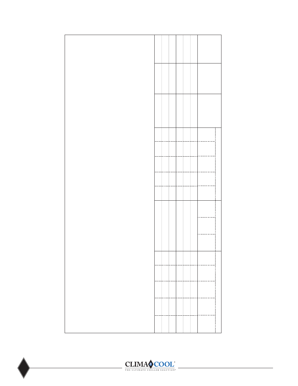
ELECTRICAL DATA : Packaged Outdoor Air Cooled Chiller: UCA020 and UCA030 Base Chiller Models
ClimaCool
Typical
Voltage
Internal Wiring - Cond. Fans
Base Model
Model #
Rated
Min.Cir.
M
axFuse
R
ec.
D
iscon.
Rated
M
in.Cir.
M
axFuse
Rated
Min.Cir.
Locked
MaxFuse
Rec.
Load
Amps
S
ize Fuse
Switch
Load
Amps
S
ize Load
Amps
R
otor
Size
Fuse
Amps
1
(MCA)
2
(MOP)
3,8
Size
4,8
Size
9
Amps
1
(MCA)
2
(MOP)
3
Amps
1
(MCA)
2
(LRA)
5
(MOP)
3
Size
4
UCA020AH
UCA020AFASAC00S
208V-230V/ 3PH/ 60HZ
83.9
93.6
125.0
110.0
150.0
6.4
8.0
12.0
38.9
48.6
300.0
90.0
70.0
UCA020AF
UCA020AFASAC00S
460V/ 3PH/ 60HZ
38.5
42.9
50.0
50.0
60.0
3.4
4.3
7.5
17.6
22.0
150.0
40.0
40.0
UCA020AN
UCA020AFASAC00S
575V/ 3PH/ 60HZ
30.8
34.3
45.0
40.0
50.0
2.7
3.4
6.0
14.1
17.6
109.0
35.0
35.0
UCA030AH
UCA030AFASAC00S
208V-230V/ 3PH/ 60HZ
129.7
144.7
175.0
175.0
200.0
9.0
11.3
16.0
60.4
75.5
425.0
125.0
100.0
UCA030AF
UCA030AFASAC00S
460V/ 3PH/ 60HZ
59.6
66.4
80.0
80.0
90.0
5.0
6.3
10.0
27.4
34.2
173.0
60.0
45.0
UCA030AN
UCA030AFASAC00S
575V/ 3PH/ 60HZ
47.7
53.2
70.0
60.0
80.0
4.0
5.0
7.5
21.9
27.4
128.0
45.0
35.0
NOTES:
1. RLA - Rated Load Amps are calculated as per UL1995.
2. MCA - Minimum Circuit Ampacity is: [ 125% of the RLA of the largest compressor motor plus 100%
of the RLA of all other concurrent motors and/or electrical loads].
3. MOP - Maximum Overcurrent Protection or Max.Fuse Size is rounded down from: [ 225% of the RLA
of the largest compressor motor plus 100% of the RLA of all other concurrent electrical loads].
4. Recommended Dual Element Fuse Sizing: Rounded up from 150% of the RLA of the largest compressor
motor plus 100% of the RLA of all other concurrent electrical loads.
5. LRA - Locked Rotor Amps are instantaneous starting amperage per compressor.
6. Module internal wiring is per NEC.
7. Voltage Tolerance Range
208-230V / 60 Hz: Min. 187V Max. 253V
460V / 60 Hz: Min. 414V Max. 506V
575V / 60 Hz: Min. 518V Max. 632V
8. MOP Device or Recommended Fusing Device for Module Power Wiring supplied by others.
These are recommended values for electrical power protection of Modules selected.
9. Disconnect Switch for Module Power Wiring supplied by others.
These are recommended values for electrical power protection of Modules selected.
Power Wiring - per Module
Internal Wiring - per Compressor