ClimaCool UCA Manual User Manual
Page 29
29
www.climacoolcorp.com
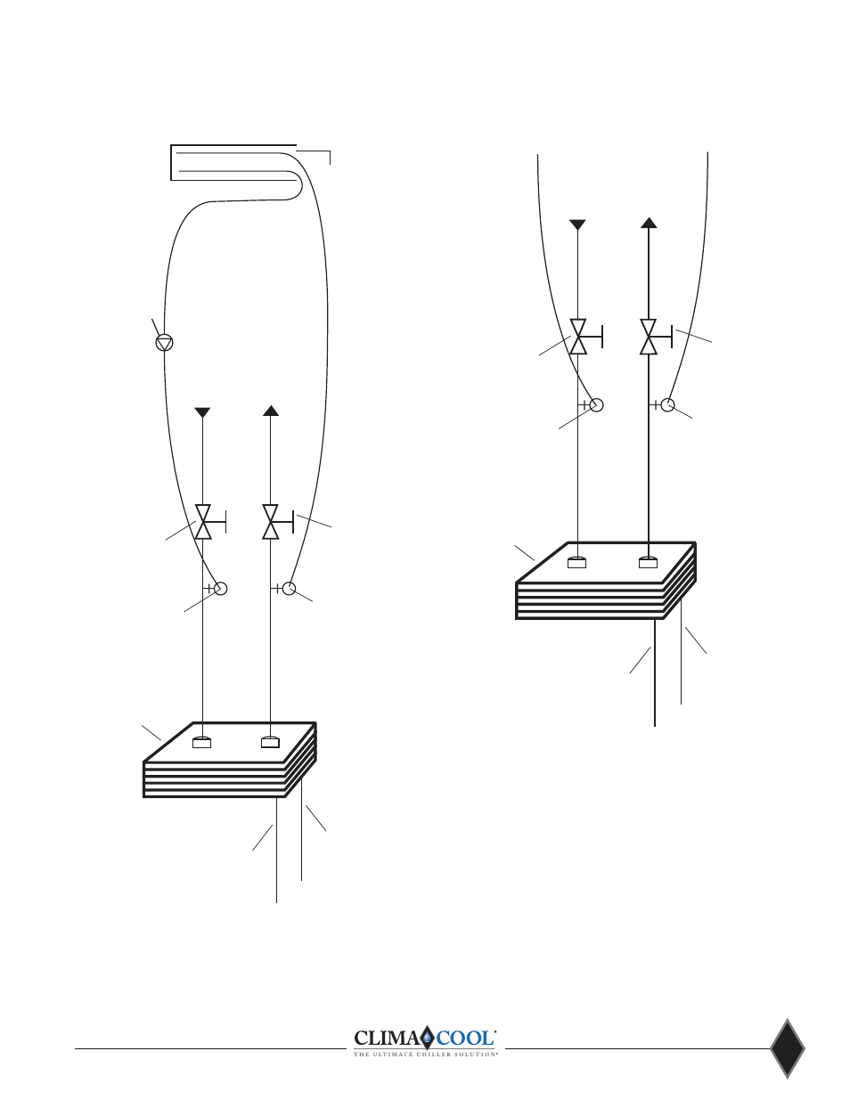
Heat Exchanger
Refrigerant Circuit #1
Refrigerant Circuit #2
Isolation Ball V
alve (2”)
Ser
vice Por
t (3/4”)
Isolation Ball V
alve (2”)
Ser
vice Por
t (3/4”)
From Cooling T
ower
To
Cooling T
ower
Header
Header
Connected to City W
ater
To
Drain
Figure 1 - City W
ater Cleaning Arrangement
Figure 2 - In Place Cleaning Arrangement
Heat Exchan
ger
Refrigerant Circuit #1
Refrigerant Circuit #2
Isolation Ball V
alve (2”)
Ser
vice Por
t (3/4”)
Isolation Ball V
alve (2”)
Ser
vice Por
t (3/4”)
From Cooling T
ower
To
Cooling T
ower
Header
Header
Connected to City W
ater
Cleaning Pump
Cleaning T
ank