Assembly and installation, Install wall plate to wall - wood studs – CHIEF TS318TU User Manual
Page 8
TS318SU/TS318TU/TS325TU
Installation Instructions
8
Assembly And Installation
Install TS318TU or TS325TU (Dual Stud) to Wall
NOTE:
If installing TS318SU, proceed to Install TS318SU
(Single Stud) to Wall section.
Install Wall Plate to Wall - Wood Studs
WARNING:
Failure to provide adequate structural strength
for this component can result in serious personal injury or
damage to equipment! It is the installer’s responsibility to
make sure the structure to which this component is attached
can support five times the combined weight of all equipment.
Reinforce the structure as required before installing the
component. The wall to which the mount is being attached
may have a maximum drywall thickness of 5/8" (1.6cm).
1.
Determine mounting location.
2.
Measure 7 1/2" above desired center line and draw a
horizontal line. (See Figure 1)
NOTE:
Hold mount up to wall at desired mounting location if
unsure about where the center line will be. The center
line of the mount will coincide with the center line of the
display. (See Figure 1)
IMPORTANT ! : Use a level to make sure wall rail (N) is
level when mounted to the wall!
3.
Drill two 13/64" holes at center of wood studs along the line
drawn in the Step 2. Holes should be 2" in depth. (See
Figure 1)
Figure 1
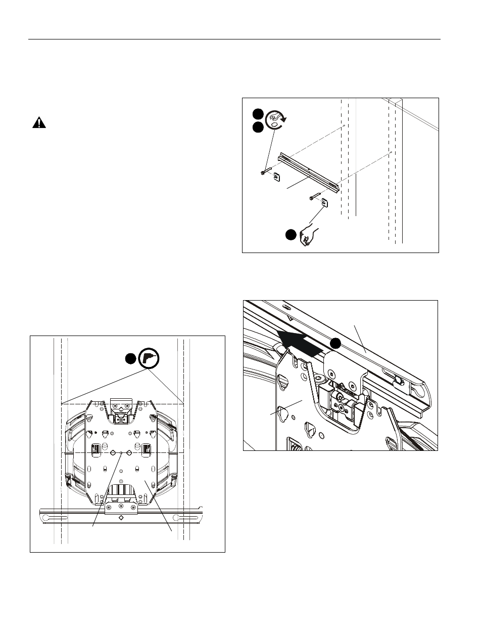
4.
Loosely attach wall rail (N) to wall using two 5/16- 2 1/2
flange head lag screws (F). (See Figure 2)
5.
Place two installation spacers (H) over two 5/16 x 2 1/2"
flange head lag screws (F). (See Figure 2)
6.
Tighten two screws (F) to secure upper wall rail (N) to wall.
(See Figure 2)
Figure 2
7.
Slide main assembly (M) onto wall rail (N). (See Figure 3)
Figure 3
8.
Center main assembly (M) over two studs.
NOTE:
Main assembly can be shifted laterally if desired. See
Lateral Shift Adjustment section for details.
9.
Drill two 13/64" holes in center of wood studs at lower
mounting holes. Holes should be 2" in depth. (See Figure 4)
10. Loosely install two 5/16 x 2 1/2" flange head lag screws (F).
(See Figure 4)
11. Place two installation spacers over two flange head lag
screws. (See Figure 4)
12. Tighten two screws to secure main assembly (M) to wall.
(See Figure 4)
3
center line
(M)
x 2
7 1/2"
16"
(F) x 2
(H) x 2
(N)
4
6
5
8
(N)
(M)