CHIEF TS318TU User Manual
Page 13
Installation Instructions
TS318SU/TS318TU/TS325TU
13
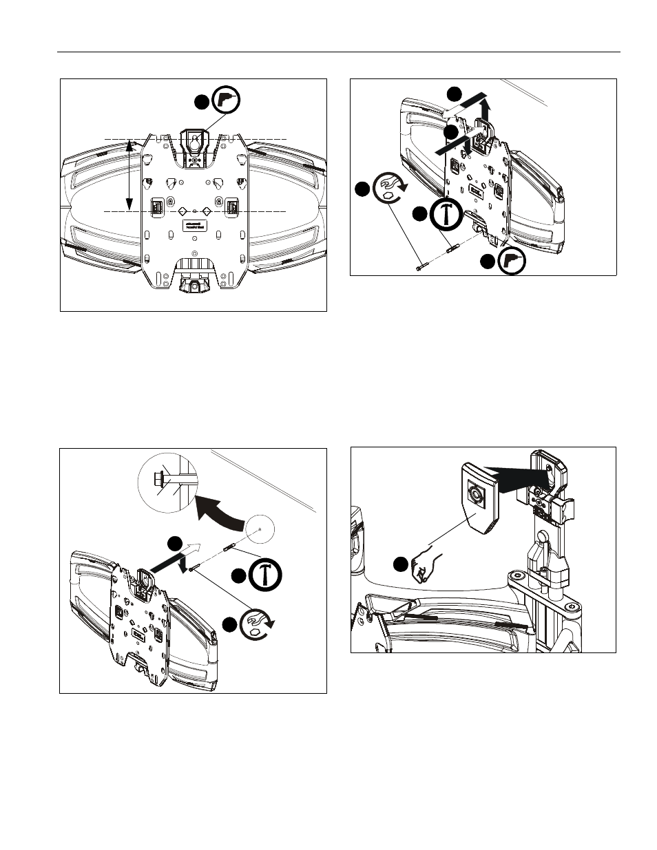
Figure 16
4.
Install one concrete anchor (G) into drilled hole. (See
Figure 17)
5.
Install one 5/16- 2 1/2" flange head lag screw (F) into
concrete anchor, leaving screw hanging out 1/2" from the
wall. (See Figure 17)
6.
Hang main assembly (M) onto lag screw (F) by latching key-
shaped hole over top of screw. (See Figure 17)
Figure 17
7.
Mark and drill one 3/8" hole at lower mounting hole location.
Hole should be 2 1/2" in depth. (See Figure 18)
8.
Remove main assembly from wall. (See Figure 18)
Figure 18
9.
Install the other concrete anchor into drilled hole. (See
Figure 18)
10. Place main assembly back onto wall. (See Figure 18)
11. Install 5/16-2 1/2" hex flange lag screw (F) into concrete
anchor to secure main assembly to wall. (See Figure 18)
12. Tighten top lag screw to fully secure mount to wall. (See
Figure 18)
13. Snap lag screw cover (U) onto wall mount over top lag
screw. (See Figure 19)
Figure 19
3
6 1/8"
(F)
6
1/2"
4
(G)
(G)
(F)
5
8
10
11
9
7
(F)
(U)
1