Install wall plate to wall – CHIEF TS318TU User Manual
Page 12
TS318SU/TS318TU/TS325TU
Installation Instructions
12
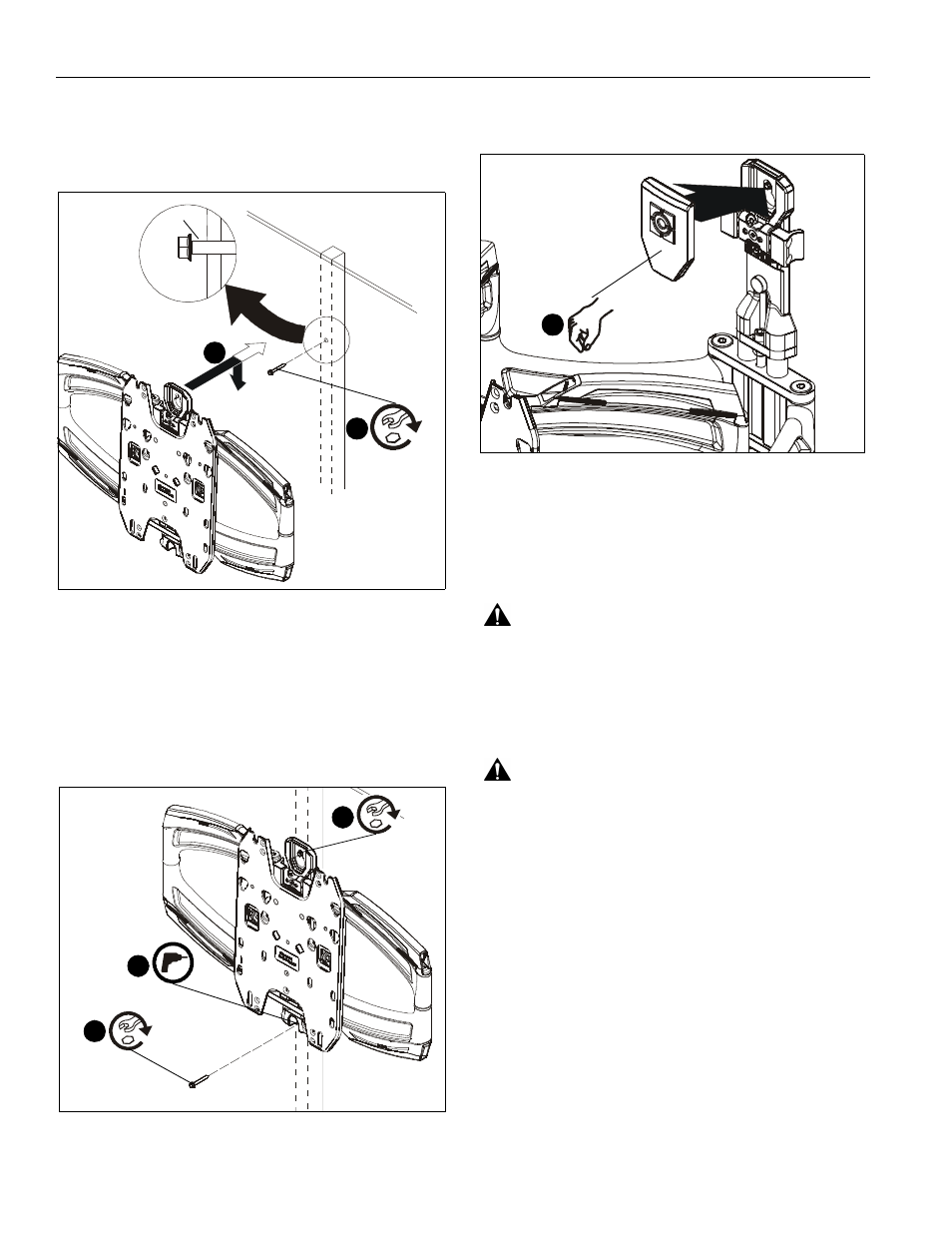
4.
Install one 5/16- 2 1/2" flange head lag screw (F) into hole,
leaving screw hanging out 1/2" from the wall. (See Figure 13)
5.
Hang main assembly (M) onto lag screw (F) by latching key-
shaped hole over top of screw. (See Figure 13)
Figure 13
6.
Mark and drill one 13/64" hole at lower mounting hole
location. Hole should be 2" in depth. (See Figure 14)
7.
Install 5/16-2 1/2" hex flange lag screw (F) into lower
mounting hole to secure main assembly to wall. (See
Figure 14)
8.
Tighten top lag screw to fully secure mount to wall. (See
Figure 14)
Figure 14
9.
Snap lag screw cover (U) onto wall mount over top lag
screw. (See Figure 15)
Figure 15
10. Proceed ahead to Interface Installation section.
Install Wall Plate to Wall
-
Hollow Concrete
Block or Poured Concrete (Important!- Read
warnings below for drywall restrictions!)
WARNING:
Failure to provide adequate structural strength
for this component can result in serious personal injury or
damage to equipment! It is the installer’s responsibility to
make sure the structure to which this component is attached
can support five times the combined weight of all equipment.
Reinforce the structure as required before installing the
component.
WARNING:
If installing to poured concrete or hollow
concrete block, the wall CANNOT have ANY drywall
covering! Do not install drywall anchors into the seam
between drywall pieces.
1.
Determine mounting location.
2.
Measure 6 1/8" above desired center line and mark a hole
at desired mounting location. (See Figure 16)
NOTE:
Hold mount up to wall at desired mounting location if
unsure about where the center line will be. The center
line of the mount will coincide with the center line of the
display. (See Figure 16)
IMPORTANT ! : Use a level to make sure main assembly
(M) is level when mounted to the wall!
3.
Drill one 3/8" hole at location marked in Step 2. Hole should
be 2 1/2" in depth. (See Figure 16)
(F)
4
5
1/2"
(F)
7
6
8
(U)
1