CEMB USA N300 User Manual
Page 82
CONDITIONS OF VALIDITY OF THE BALANCING TOLERANCE GRAPH
1. The balancing values refer to the entire rotor; if there are two
planes of correction and if the rotor is approximately symmetrical,
each correction plane should be allotted a tolerance value equal
to half the value found, as long as the correction planes are
symmetrical with respect to the barycentre and the pedestals;
in
the case of marked asymmetry in the rotor or in the position of the
correction planes, the residual unbalance must be divided
accordingly between the two planes of correction.
2. The tolerance values arc valid both for static and for couple
unbalance.
3. A rotor should be considered to be rigid over its complete range of
service speeds and in the actual working conditions of the machine
itself (bearings, pedestals, bedplates, foundations, couplings with
other rotors, drive elements, etc.).
NOTE 1 - Balancing grades 0,4 and 1
For class 0,4 and 1 rotors, balancing tolerance must normally be
checked with the direct experimental method.
The influence of the means of rotor drive and of the bearings may be
significant.
NOTE 2 – Use of auxiliary equipment
For rotors that must be mounted on auxiliary shafts or flanges for
balancing,
the tolerances shown are only meaningful if, as well as the
unbalance of the auxiliary shaft or flange, the play of the mounting and
the working tolerance of the piece are checked for their concentricity
with the rotational axis, both for the residual unbalances and of the
ultimate shaft. The sum of the residual unbalances and of the plays,
converted into eccentricity values, must, of course, be lower than the
balancing tolerance, as the balancing accuracy obtained would otherwise
be purely illusory.
NOTE 3 - Assembled rotors
For assembled rotors the unbalance of the component parts must be
summed together vectorially, also bearing in mind the unbalance that
derives from the mounting (machining tolerances, clearances, keys,
set screws, etc.).
The unbalance resulting after the assembling should be lower than that
indicated by the graphs for the complete rotor; if it is not, the rotor
should be balanced after assembly, selecting two suitable planes of
correction.
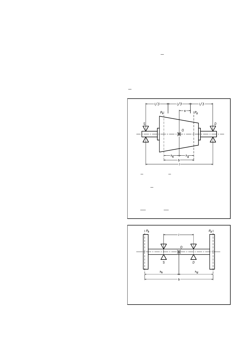
DIVIDING THE PERMISSIBILE RESIDUAL
UNBALANCE BETWEEN TWO CORRECTION
PLANES
In most rotors, a reasonable division of the total permissible
residual unbalance
U
of the rotor is possible between the two
correction planes using one of the following methods; choose
the method according to the conditions specified.
Us
and Ud are used to indicate the respective permissible
residual unbalances for the left and right correction planes (see
figures).
O
indicates the rotor’s barycentre.
1) If
l
b
l
<
<
3
;
3
l
s
<
with
d
s
h
h
≅
we can consider
U
U
U
d
s
2
1
=
=
With
d
s
h
h
≠
but
b
h
b
s
7
,
0
3
,
0
<
<
we can consider
U
b
h
U
d
s
=
;
U
b
h
U
s
d
=
2) If
l
b
>
it is advisable to consider a greater value of
overall unbalance
to be divided as above
DIRECT EXPERIMENTAL METHOD
The most accurate and safest value of the maximum permissible
residual unbalance can only be obtained with direct experiments.
To do this, balance the rotor on a balancing machine as accurately
as possible, then fit it on its ultimate machine in service
conditions. In successive tests, add increasing unbalances, until
the vibrations of the pedestals or of the machine become
significant. Now establish the maximum permissible unbalance
in relation to the value found, e/g. one third.
This testing must be systematic, so as to take all possible cases
of vibration and all possible conditions of the rotor and of the
position of the added unbalances into consideration.