3 - recalculation of the unbalance, 4 - result of measurement – CEMB USA K10 (D) User Manual
Page 10
I 0215 - 10
GB
5.3 - RECALCULATION OF THE UNBALANCE
Press
after new setting of the measurement.
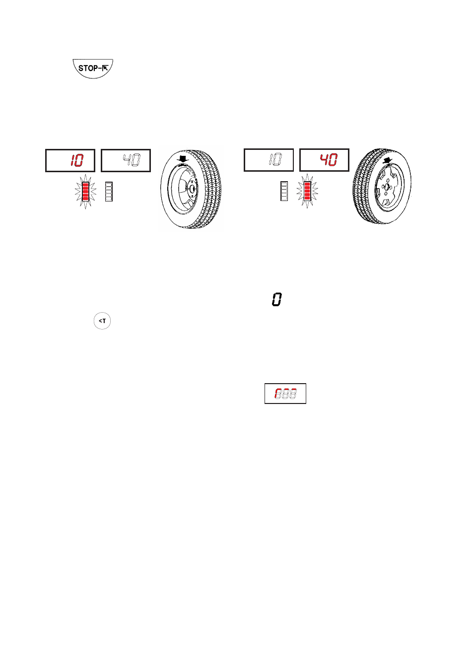
5.4 - RESULT OF MEASUREMENT
Fig. 7
Correction of inner side
Correction of outer side
After performing a balancing spin, the amounts of unbalance are shown on the digital readouts.
Digital readouts with LED ‘s 3 - 4 lit up indicate the correct angular wheel position to mount the counterwei-
ghts (12 o’clock position). If the audible alarm is enabled (see
FUNCTION MENU MANAGEMENT
) the acquisition
of the correction position is confirmed by a “beep” alarm.
In the event of unbalance less than the selected threshold value , is displayed in place of the unbalance
value , with
it is possible to read the values below the selected threshold gr. by gr.
NOTE: In the event of wheels with diameter less than or equal to 13” and at temperature conditions near
0°, the wheel balancer automatically engages a special measuring cycle involving two successive
measurements. The precision of unbalance values and the reliability of the wheel balancer are
unaffected. This type of operation is reset every time the wheel balancer is started.
If at the end of any balancing run, the flashing symbol
appears, manually turn the wheel
until unbalances are displayed.