CEMB USA C72_2SE (B) User Manual
Page 16
I 0226 - 16
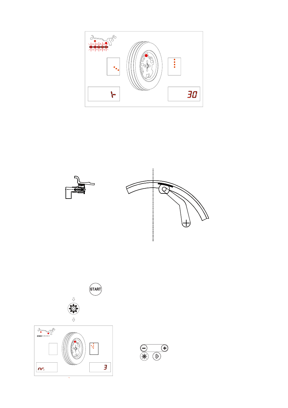
Fig. 17
GB
- Bring the wheel into correct angular position.
- Move the gauge until the display corresponding to the selected correction plane shows the unbalance
value again.
- Rotate the rim until the correct weight lies against the rim.
- The fact that the weight application position is no longer vertical (fi g. 16) is offset automatically.
N.B. : It is not possible to put automatically the correction weight in the Fig.8/Pos.B position; always
rotate the rim in Fig.5/Pos.A
Fig.
16
5.4.2 - RESOLUTION OF THE UNBALANCE (SPLIT)
SPLIT only has meaning in the case of static unbalance or ALU-S on outside. It serves for hiding any
stick-on unbalance correction weights behind the rim spokes.
PRESETTING:
Position
reached
on the
external side
Fig. 15
Perform a balancing spin (
)
- Place any spoke in the 12 o’clock position
-
set the number of spokes
-
/
confi rm the settings enabling unbalance
split