5 router stop switch – Castle TSM-21 Serial 64234 and above (Bosch) Operator Manual User Manual
Page 35
CASTLE, INC
TSM-21 OWNERS MANUAL V2.0
Page 35 of 41
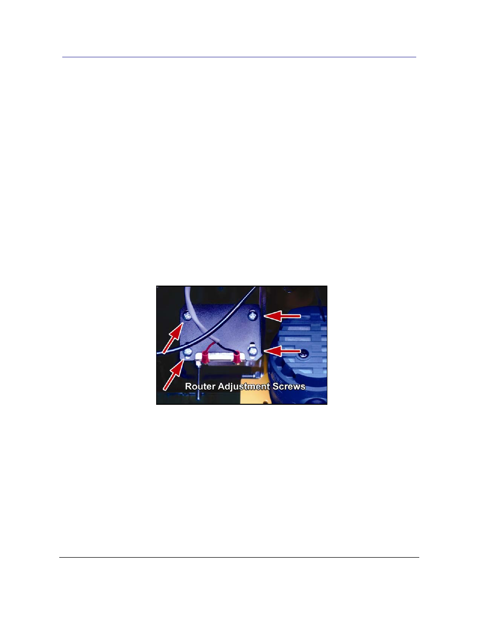
7.5 Router Stop Switch
The Router Stop Switch consists of a magnet (no wires) mounted near a magnetic reed switch
(with wires) on the Router Stop Plate. At the full extension of the routing stroke, a tab on the
Motor Carriage interrupts this switch to signal the start of the drilling stroke. If the clamp doesn’t
release and the pilot drill hasn’t come out, then the Router Stop Switch may require a simple
adjustment.
• Open the rear door of the machine and observe if the Motor Carriage has stalled with the
router fully extended into the pocket. If the carriage is fully extended then it’s likely that the
magnet is too close to the reed switch.
•
Turn the power to the machine off.
• Loosen the two lower screws on the Router Stop Plate and slide the magnet (no wires)
approximately a
1
/
16
” further away from the reed switch. (Fig 27)
Fig 27
• Manually pull the Motor Carriage toward the rear of the machine to ensure that the tab does
not strike the magnet or the magnetic reed switch.
• Turn on the power to the machine and make a test pocket.
• If the router still stalls in the pocket test with a continuity tester as described in Section 7.2
Safety Switch (page 33). If no continuity registers, a new switch assembly will be needed.