Appendix k: can bus wiring - single device, 5 pin connector type – MoTeC M84 User Manual
Page 80

78 Appendices
MoTeC
Appendix K: CAN Bus Wiring - Single Device
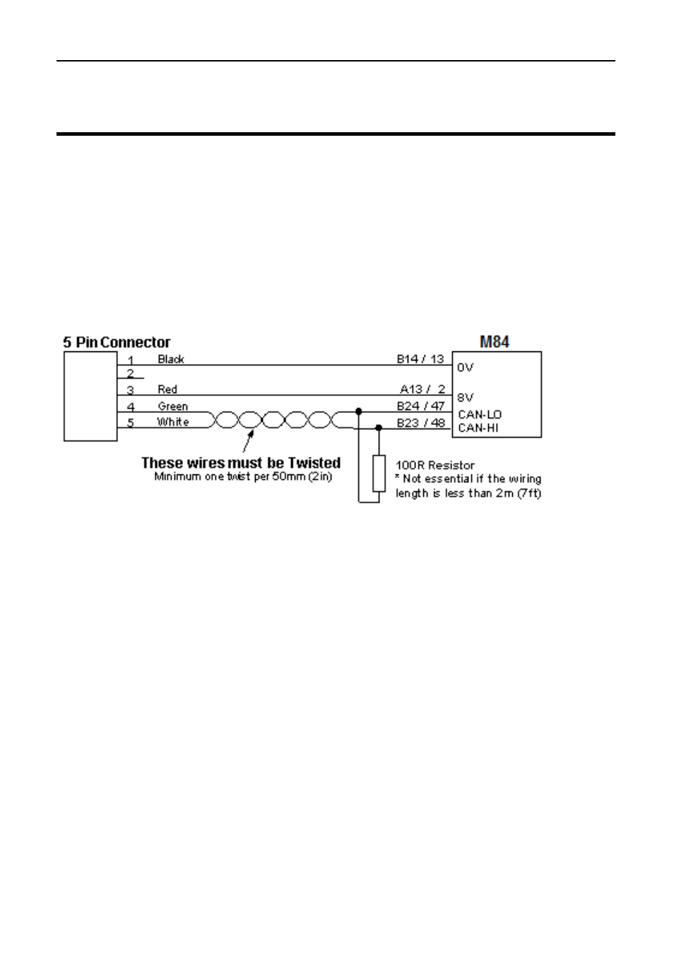
When a single device (such as an ECU) is connected to the CAN bus the
wiring scheme shown below may be used to provide a connection point for
the MoTeC CAN cable.
If the wiring length is less than 2m (7ft) the terminating resistor is
recommended but not essential.
If other devices are connected to the CAN bus a special wiring scheme is
required. See CAN Bus Wiring Multiple Devices.
5 Pin Connector Type :
Deltron 716-0-0501 (Non
Latching)
Neutrik NC5FDL1 (Latching)
See also other documents in the category MoTeC Hardware:
- ADR (25 pages)
- ACL VIM (99 pages)
- ADL EDL (81 pages)
- ADL2 EDL2 (82 pages)
- ADL3 EDL3 (80 pages)
- AFM1 (20 pages)
- BR2 BTX (47 pages)
- BRX (21 pages)
- C125 (89 pages)
- C185 (85 pages)
- CDL3 (86 pages)
- DBW-4 (21 pages)
- Display Creator (66 pages)
- E888 (30 pages)
- GPS-BL1 (8 pages)
- GPS-G1 (7 pages)
- GPS-L5 (8 pages)
- Interpreter (37 pages)
- Knock SKM (36 pages)
- LTC (39 pages)
- M1 Series Quick Start Guide (1 page)
- M1 Tune User Manual (77 pages)
- M4 (63 pages)
- M400 (101 pages)
- MDC (22 pages)
- MDC2 (20 pages)
- MDD (48 pages)
- PDM16 (61 pages)
- PLM (59 pages)
- PWC Plug-In ECU (91 pages)
- Screwdriver ECU (5 pages)
- SDC3 (24 pages)
- SDL (70 pages)
- SDL3 (76 pages)
- Snowmobile Plug-In ECU (46 pages)
- VCS (36 pages)