Dialight LBW1X1X DuroSite LED Low Bay User Manual
Page 3
Document No: 9100-127-1434-99 Rev B
Page 3 of 5
1501 Route 34 South, Farmingdale, NJ 07727
Tel: (732) 919-3119 Fax: (732) 751-5778 www.dialight.com
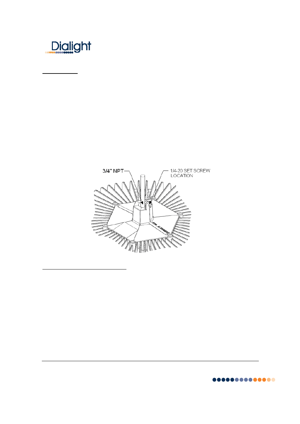
Pendent Mount Installation Steps:
•
For maximum long term reliability and light output, the light must be installed in free air.
o
The Low Bay fixture design incorporates an over-temperature control circuit that
reduces input power should internal temperatures reach a maximum level. As a
result, light output may be reduced.
•
The Low Bay fixture is threaded for 3/4” NPT in order to be assembled to conduit.
o
Calculate and measure required conduit length.
o
Feed the power cable through the conduit and into the junction box.
o
Attach the fixture to the conduit (using Teflon tape or pipe sealant).
o
Insert 1/4-20 anti-rotation screw in order to secure the fixture to the conduit.
•
Connect power cable conductors as follows:
o
Green wire connects to Safety Ground.
o
White wire connects to Neutral
o
Black wire connects to Live
•
Restore power and verify operation.
Interfacing to an Occupancy Sensor:
The Dialight Low Bay fixture is ideally suited for control by an occupancy sensor in order to
maximize energy savings based on its instant-on behavior and low power consumption.
Instructions for connecting the High Bay fixture to an occupancy sensor are listed below.
WARNING: TO BE INSTALLED AND/OR USED IN ACCORDANCE WITH APPROPRIATE
ELECTRICAL CODES AND REGULATIONS.
WARNING: CONTROLLING A LOAD IN EXCESS OF THE SPECIFIED RATINGS OF THE
OCCUPANCY SENSOR COULD DAMAGE THE UNIT AND POSE RISK OF FIRE, ELECTRIC
SHOCK, PERSONAL INJURY, OR DEATH. CHECK LOAD RATINGS TO DETERMINE THE
UNIT’S SUITABILITY FOR YOUR APPLICATION.
NOTE: SEE OCCUPANCY SENSOR INSTALLATION INSTRUCTIONS FOR ADDITIONAL
INFORMATION.