Configure the communication (com) port settings – DE-STA-CO eSwitch Programmable Limit Switch User Manual
Page 8
8
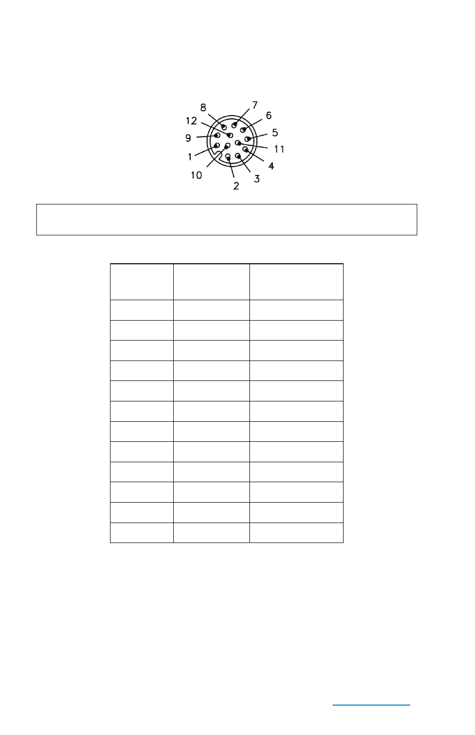
3. eSwitch Data Connector Pin Numbers
NOTE: All outputs must be connected to COMMON (“daisy-
chained”) to complete the circuit.
Data connector pin assignments
Output
Name
Turck Wire
Color *
Data Connector
Pin Number
+24V IN
TN (Tan)
10
COMMON
BK (Black)
11
OUT1
WH (White)
1
OUT2
BN (Brown)
2
OUT3
GN (Green)
3
OUT4
YE (Yellow)
4
OUT5
GY (Gray)
5
OUT6
PK (Pink)
6
OUT7
BU (Blue)
7
OUT8
RD (Red)
8
not used
VT (Violet)
12
not used
OG (Orange)
9
* Wire colors are for Turck RKC12T 12-pin cable
Configure the Communication (COM) port settings
1. Connect the eSwitch to the computer with the USB cable. You
will need to provide power to the eSwitch
2. In Windows, open the Control Panel, select System and open
the Device manager.