DE-STA-CO 115RSD User Manual
Page 9
its mating surface on center post (7).
18. Install shims (5) in housing (1).
19. Insert follower wheel (4) down through
opening of housing (1).
20. Install quad ring (27) in groove of output
bearing retainer (6).
21. Apply EXP 222 grease on quad ring (27)
and its mating surface on follower wheel (4).
22. Apply a bead of silicone around follower
wheel opening of housing (1).
23. Install shims (5) on housing (1).
24. Apply a bead of silicone under output
bearing retainer (6).
25. Install output bearing retainer (6).
26. Install screws (32) using Permabond thread
locking liquid as recommended in the
General Service Manual.
27. Wipe off all excess silicone.
OIL SEAL INSTALLATION
Install new oil seal as described in the General
Service Manual.
LUBRICATION
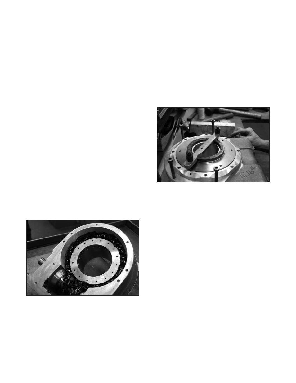
Fig.10Lubrication
With housing (1) upside down, fill housing with 16
oz. of EXP 222 grease, so that grease is level with
top of cam followers (25).
BOTTOM COVER INSTALLATION
A. Install two dowel pins (1b) in the cover for
alignment.
B. Apply a bead of silicone around bottom cover
opening of housing and install bottom cover.
C. Install screws (1a) using Permabond thread
locking liquid as recommended in the
General Service Manual.
SEAL INSTALLATION
Fig.11Sealinstallation
A. Apply EXP 222 grease to outside of seal
(9, 26).
B. Install seal around center post (7), taking
care to depress it evenly so that rubber seal
does not fold.
SERVO MOTOR INSTALLATION
A. Position clamp collar (13) on input shaft (15). The
collar should be positioned so collar screw will be
accessible through opening in mounting plate.
B. Position mounting plate and servo motor on
housing (1).
C. Working through opening in mounting plate,
tighten shaft collar screw (29).
D. Install motor mounting screws (23) using
Permabond thread locking liquid as
recommended in the General Service Manual.
8