Spool schematic, Typical installation schematic – BRAND Hydraulics LS DIRECTIONAL CONTROL VALVES User Manual
Page 3
04/14
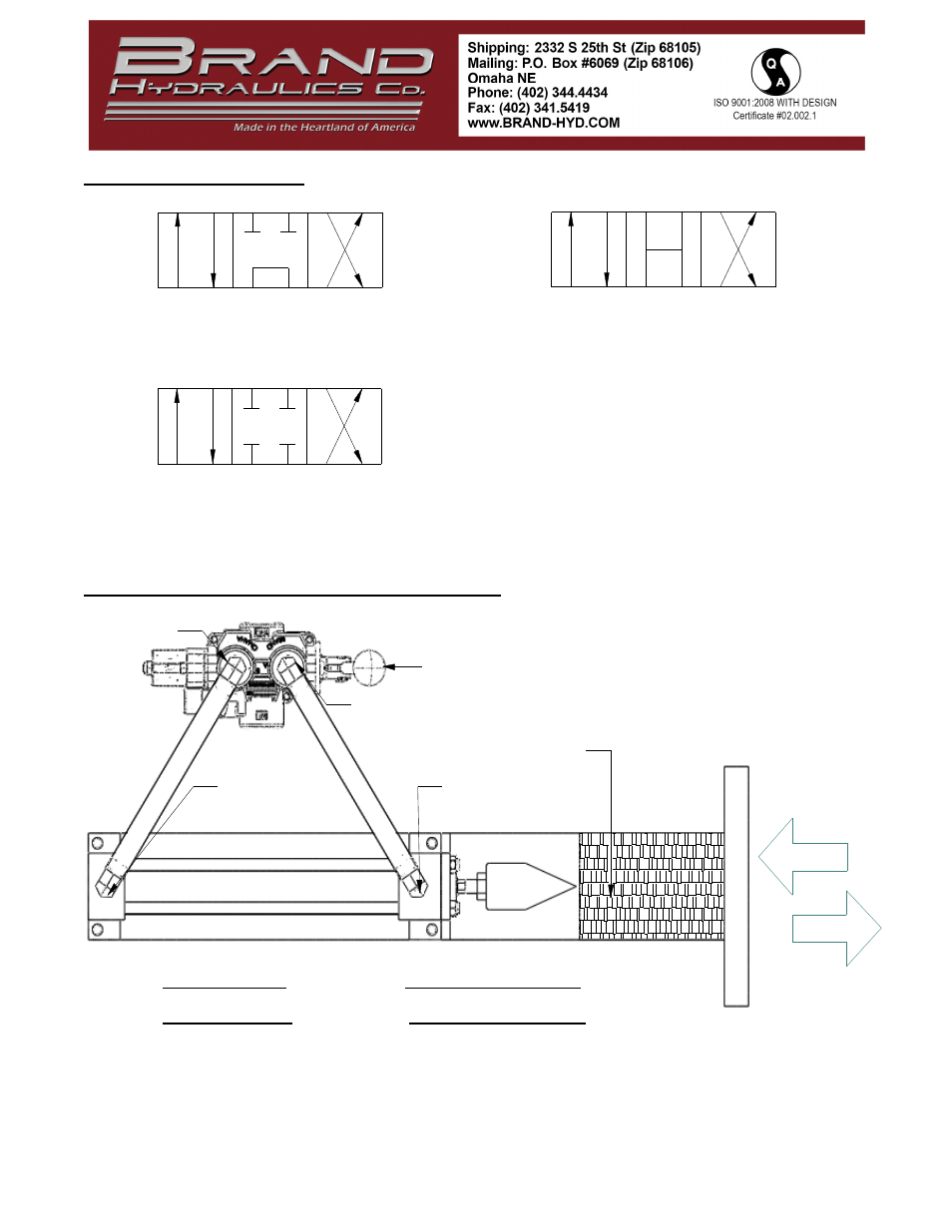
T
P
A
B
Tandem Center 4-way (T4) - Powers cylinder or
motor in both directions. Pump unloads to tank
when spool is in neutral. Cylinder or motor
blocked when spool in neutral.
Open Center 4-way (O4) - All of the ports are
connected to tank when the spool is in neutral.
Allows cylinder to move or motor to rotate
when spool is in neutral.
B
A
P
T
Closed Center 4-way (C4)- All ports are blocked
in neutral. Blocks cylinder or motor in neutral.
Required for use with pressure compensated
pump.
P
T
A
B
"A" PORT
"B" PORT
LS VALVE
LOG
CYLINDER CAP
END
CYLINDER ROD
END
NOTE:
PULLING LEVER HANDLE WILL PRESSURIZE "B" PORT
•
AND EXTEND CYLINDER
PUSHING LEVER HANDLE WILL PRESSURIZE "A" PORT
•
AND RETRACT CYLINDER.
LEVER HANDLE WILL KICK BACK TO NEUTRAL
•
WHEN CYLINDER IS FULLY RETRACTED
RETRACT
EXTEND
SPOOL SCHEMATIC:
TYPICAL INSTALLATION SCHEMATIC: