Dimensional data, Flow & pressure information – BRAND Hydraulics DCF DIRECTIONAL CONTROL VALVE User Manual
Page 2
04/14
0.0
1.4
2.8
4.1
5.5
6.9
8.3
4
19
34
53
68
87
102
121
136
155
170
0
20
40
60
80
100
120
1
5
9
14
18
23
27
32
36
41
45
P
re
s
s
u
re
(
b
a
r)
Flow (lpm)
P
re
s
s
u
re
(
p
s
i)
Flow (gpm)
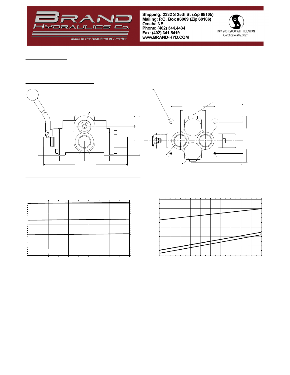
Neutral Flow Pressure Drop
DCF M SPOOL
DCF TM SPOOL
DC T4 SPOOL
B
R
A
N
D
OMAHA
HYD
N
E
B
I N
OUT
A
B
1
0
.3
0
"
[2
6
2
]
2.70" [68.6]
2.70" [68.6]
1.93" [49.0]
9.05" [229.8]
1
.6
3
"
[4
1
.3
]
1
.1
9
"
[3
0
.2
]
4
.2
5
"
[1
0
8
.0
]
1
.3
8
"
[3
4
.9
]
2
.0
0
"
[5
1
]
0
.7
0
"
[1
7
.7
]
5
.0
1
"
[1
2
7
.2
]
2.72" [69.0]
INLET
PORT A
OUTLET
PORT B
RELIEF ADJUSTMENT
4.75" [120.7]
4X Ш0.27" [Ш6.7]
Pressure vs. Flow for Pilot Relief (DCF)
0
500
1000
1500
2000
2500
1
3
9
18
24
30
Flow (gpm)
P
re
s
s
u
re
(
p
s
i)
0
34
69
103
138
172
3.8
11.3
34.0
68.0
90.7
113.4
Flow (lpm)
P
re
s
s
u
re
(
b
a
r)
Relief is set at 6 gpm
Spool Information - All DCF’s are built with Iosso plated spools to improve wear and corrosion resistance. For highly
corrosive environments, i.e. marine applications, we recommend using a stainless steel spool. To order a valve with a
stainless steel spool simply add “SS” to the end of the model code.
DIMENSIONAL DATA
FLOW & PRESSURE INFORMATION