Carlon Brass Adjustable Floor Box Kit - Low Res User Manual
Page 3
Installation – New Work Bracket
1. The new work metal bracket may be installed on
the floor joist below a 3/4 inch subfloor. When a
thicker subfloor is used we recommend cutting a
hole in the subfloor using the box as a template
and adjacent to the joist so the mounting screws
will engage the joist as well as the subfloor. Use
the four (4) #6 1-3/4" self-tapping screws
suppled with the kit to mount the bracket.
2. If the new work bracket is installed from the
underside of the joist, ensure the alignment with
the box and opening before installing the brack-
et. Use the four (4) #6 1-1/4" self-tapping screws
supplied with the kit to mount the bracket.
3. The romex wire can then be pulled through the
desired clamp and the box aligned in the bracket
slide. Ensure the adjusting screw is aligned on
the bracket and rotate the screw clockwise using
an electric or pneumatic POWER screw gun.
(The adjusting screw can be turned manually
with a screwdriver, but this is a self-tapping
screw that is cutting threads into hardened steel
and it will be very, very difficult.)
4. Adjust the box flush to
1
/
2
" above floor, leaving
sufficient room to complete the installation.
5. Wire the receptacle in accordance with the
National Electrical Code. Attach a short length of
green or un-insulated grounding wire to ground
lug on the receptacle. Connect ground wire from
receptacle and green ground wire provided with
brass cover to ground wire entering the box
using appropriate wire connector.
6. Align the receptacle on the recessed bosses and
place the cover on the box with the outlet caps
open. Push cover into the box until bottom of
cover flange is flush with top of box.
7. Insert the two (2) 6-32x1 inch flat-head machine
screws in the holes in the cover, ensuring that
the screw is aligned with and captivates the
receptacle. DO NOT OVER TORQUE. Tighten the
screws to a maximum of 6 to 8 inch pounds.
Ensure bottom of cover flange is flush with top
of box.
8. Remove the threaded plug on the brass cover
that hides the adjusting screw opening and set it
aside where it will not be misplaced.
9. Using the adjusting screw, adjust the assembly
so cover flange is flush with floor. Do not pre-
load the cover against the floor covering. Place
the threaded plug you previously set aside in the
adjusting screw opening and tighten.
10. Turn the coin slot lock in the center of the cover
in either direction to lock the outlet caps.
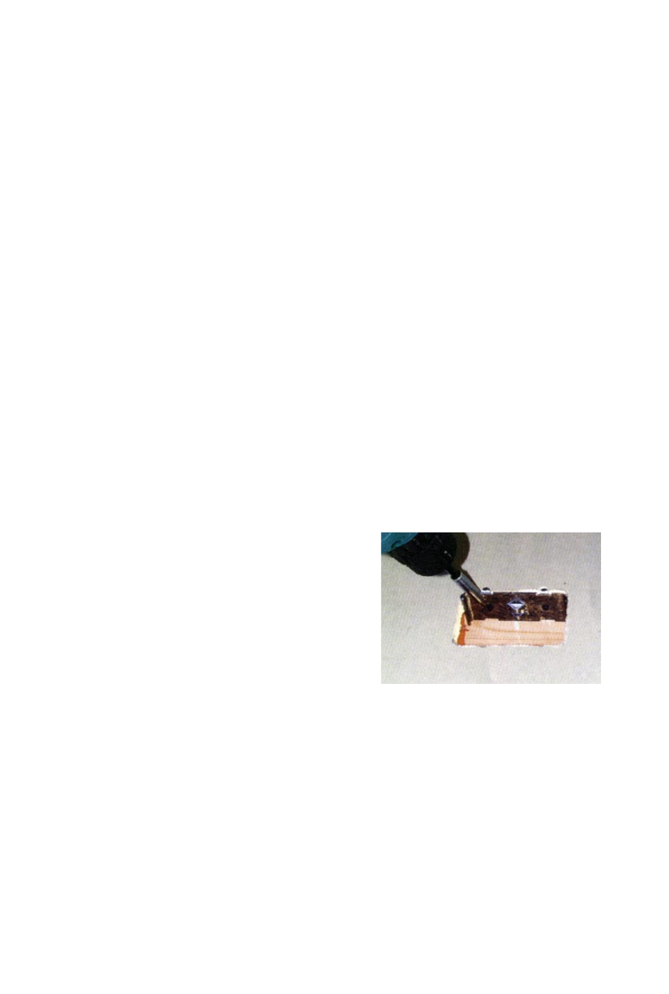
Installation – Old Work Bracket
1. As indicated in the prior instructions,
ensure there is sufficient depth of
the floor covering to install the old
work bracket. If not, the bracket
must be installed adjacent to a joist
where the screws will engage the
joist/flooring for support.
2. Use the box as a template and cut
out an opening in the floor cover.
3. Place the bracket on the side of the
opening where it is to be mounted
with the two tabs up and resting on
the surface. (Be careful not to drop
the bracket into the opening.)
4. Install the bracket using the two (2)
square drive trim head screws
provided in the kit. Since the screws
are installed at an angle, there may
be a small part of the screw head
that protrudes. This is to be antici-
pated and will not interfere with the
installation of the box.
5. Use the installation instructions for
the new work bracket from this point
forward starting with step 3.
Old work bracket
installation for tight
locations or cut-in
situations
MAINTENANCE
To ensure continued service, it is
recommended that the sealing surfaces
of the caps and cover be kept free of
debris.
NOTE: Ground brass cover using green
grounding screw and ground
wire provided.
Gross Automation (877) 268-3700 · www.carlonsales.com · [email protected]