Voltage failure indication, Current monitoring, Digital i/o – B&K Precision MDL Series - Manual User Manual
Page 64
64
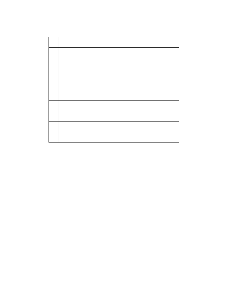
Table 3 - Module Terminal Pinout
Pin
Signal
Description
1
GND
Ground
2
VF
Voltage fault indication terminal
3
DI
Digital input terminal
4
DO
Digital output terminal
⃝
I OUT
Current monitoring output
5
SENSE +
Voltage remote measuring terminal (+)
6
SENSE -
Voltage remote measuring terminal (-)
7
EXT_PRG+
External analog controlling terminal (+)
8
EXT_PRG-
External analog controlling terminal (-)
Voltage Failure Indication
When the electronic load is under OVP or reverse protection condition, pin 2 (VF) will output a high
level signal.
Current Monitoring
The current monitoring terminal will output 0-10 V analog signal accordingly to 0 - full range of the
input current. You can connect an external voltmeter or an oscilloscope to display the input
current’s change.
Digital I/O
Digital I/O is pin 3 and pin 4 shown in Figure 31 and only used in remote control. The digital input
terminal (pin 3) can detect a high/low level signal. The digital output terminal (pin 4) can output a
TTL high/low level signal. It is a universal output terminal and can be used to control an external
instrument.