頁面 15 – Avlex ACT-818 Wideband Single-Channel Digital Receiver User Manual
Page 15
24
25
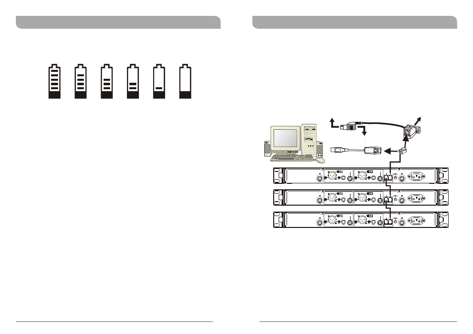
1. MIPRO ACT receivers are fitted with an ACT-BUS interface to enable remote control
and monitoring via a PC-based control system. To enable this to communicate, an
optional MIPRO interface adapter and software package is required.
2. Wiring Instructions
! Network interfacing of the ACT-818/ACT-828 receivers is achieved via the REMOTE
IN of the Network Interface Connector
. This enables the receiver(s) to be linked
to a computer using a MIPRO-DVJ (Serial) or MIPRO-DVU (USB) interface
connector. Using the RS-232 or USB connector, you can link to a computer through
the RS-232 COM port or USB port. (See diagram below)
! Plug one side of the supplied telephone-type cable (RJ-11 connectors) to the
REMOTE OUT socket of the on the rear of the receiver and the other end of the
cable to the REMOTE IN socket on the rear of the second receiver. Repeat this
connection for each receiver in the system as per the illustration above. Finally,
connect the REMOTE IN socket on the rear of the first receiver to the MIPRO-DVU
or MIPRO-DVJ.
! The system can link, monitor and control up to 64 receiver channels
simultaneously.
! The connection cable to the computer can be up to 300 metres (330 yards) in
length. However, signal stability and data transmission speed decreases as cable
distance gets longer. RF it is recommended not to exceed 100m (110 yards) to
maintain the highest data quality as well as a high transmission speed.
MIPRO DVU
MIPRO DVJ
OR
RX1
RX2
RX3
PC
Computer Network Interface Operation
BA: Transmitter Battery Meter (receiver display)
The battery meter illuminates when the transmitter is powered ON. The LCD battery
meter gives a percentage (%) indication of remaining battery life, as shown above.
Recharge the transmitter battery (or replace with a charged battery pack) immediately
when battery indicators fall to 10% (1 bar showing as indicated above).
100%
90%
80%
40%
10%
0%
BA
BA
BA
BA
BA
BA
+8V DC BIAS
ANTENNA B
BALANCED OUT CH1
BALANCED OUT CH2
LIFT
LIFT
OUTPUT CH1
OUTPUT CH2
SPDIF OUT CH1
SPDIF OUT CH2
GND
GND
MIC
MIC
LINE
LINE
This connector can not be connected
to telecommunication networks.
REMOTE
OUT
IN
(12~15V)
DC INPUT
+8V DC BIAS
ANTENNA A
AC INPUT: 100~240V
MADE IN TAIWAN
+8V DC BIAS
ANTENNA B
BALANCED OUT CH1
BALANCED OUT CH2
LIFT
LIFT
OUTPUT CH1
OUTPUT CH2
SPDIF OUT CH1
SPDIF OUT CH2
GND
GND
MIC
MIC
LINE
LINE
This connector can not be connected
to telecommunication networks.
REMOTE
OUT
IN
(12~15V)
DC INPUT
+8V DC BIAS
ANTENNA A
AC INPUT: 100~240V
MADE IN TAIWAN
+8V DC BIAS
ANTENNA B
BALANCED OUT CH1
BALANCED OUT CH2
LIFT
LIFT
OUTPUT CH1
OUTPUT CH2
SPDIF OUT CH1
SPDIF OUT CH2
GND
GND
MIC
MIC
LINE
LINE
This connector can not be connected
to telecommunication networks.
REMOTE
OUT
IN
(12~15V)
DC INPUT
+8V DC BIAS
ANTENNA A
AC INPUT: 100~240V
MADE IN TAIWAN
Connect to keyboard jack on PC
Connect to
RS-232 jack on PC
Connector of keyboard
should plug in here
Connect to USB
jack on PC
Wideband Digital Receivers
Wideband Digital Receivers