atwood Levelegs 5th Wheel Leveling IOM User Manual
Page 8
- 8 -
control pad.
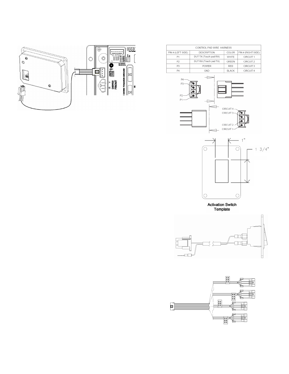
Signal Wire Harness / Activation Switch
NOTE: It is important for this harness to be plugged in
after all other wires are installed.
1. Locate the activation switch next to the installed auto position
control pad allowing clearance for both the controller and switch
mounting surfaces. Provide a space with the dimensions shown
in the figure to the right at desired location. Note: The clearance
for the activation switch is not as tight.
2. Connect the 20 AWG wire ring terminal to the positive terminal
(labeled P1 VBATT) on the controller along with the power
connection (see “Power Connections” below) using the #10
conductive washer, #10 lock conductive washer, and
10-32 conductive nut.
3. Plug in the harness (six pin terminal) to the
corresponding connector on the control board.
Leveler Sensor Connections
• Use the 22 AWG connector (four harnesses feeding
back to a single terminal at the control board) to connect the leveler signals to the control
Board.
1. Plug in the harness (six pin terminal) to the
control board.
2. Run the four harnesses from the control board
compartment to each of the corresponding
leveler locations.
3. Plug in the four harnesses into the sensor
terminal for the corresponding leveler motor.
4. Secure the harnesses underneath the RV.
TOUCH PAD HARNESS