Features – Atec Wallace-Tierman-65-120 User Manual
Page 2
Features
2
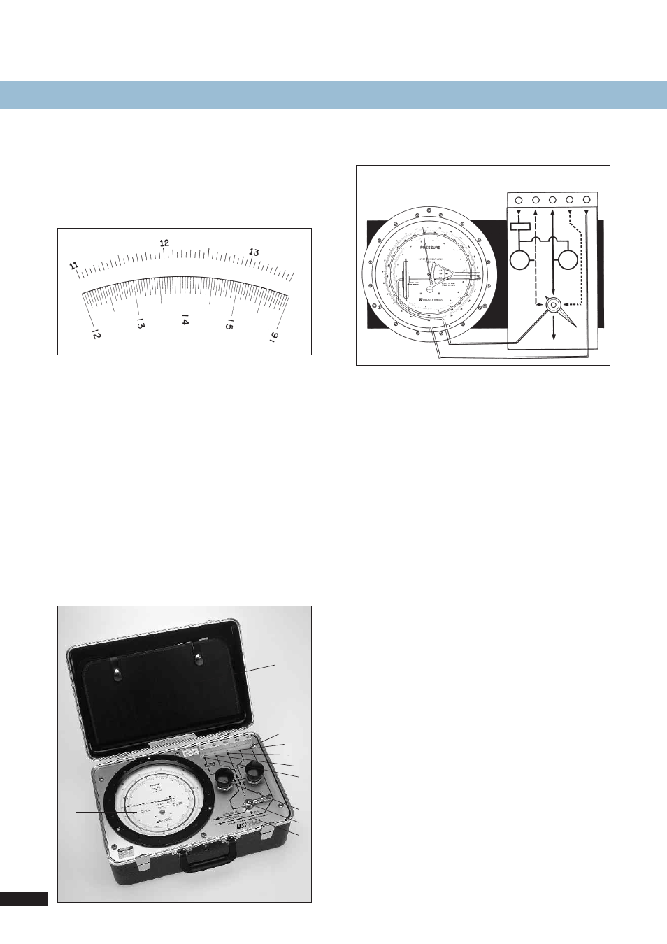
Clear, Accurate Readout
Sharply defined graduations, a 45-inch (1140 mm) scale length
over two pointer revolutions, and a knife-edge pointer facilitate
precise readouts. All scale calibrations are individually plotted
and hand marked to produce a dial custom fitted to the pres-
sure element and mechanism of that gauge.
Connections for different Pressure readouts
For gauge pressure:
test pressure is applied to the capsule through the appropriate
P connection; the case is open to atmosphere through S.
For differential pressure:
high test pressure is applied to the capsule through the appro-
priate P connection. Low test pressure is applied to the case
through S.
For absolute pressure:
test pressure is applied to the capsule through the appropriate
P connection and the case is continuously subjected to full
vacuum through S.
For vacuum:
the capsule is open to atmosphere through connection P; the
case is connected to test vacuum at S.
For positive and negative pressures:
test pressure is applied to the capsule through the appropriate
P connection and the case is open to atmosphere through S.
Engineered for perfomance
The gauge housing is heavy cast aluminum with a tempered
glass dial cover. A built-in pressure-relief valve has a dumping
capacity which protects the case against overpressures to 10
times the maximum pressure rating. A separate pressure-relief
valve protects the capsule mechanism. The gauge is mounted
inside the carrying case on rubber-padded shock mounts. The
carrying case is constructed of strong but lightweight molded
ABS that flexes to absorb shock from impact.
Compact, built for on-site service
The W&T Portable Pneumatic Calibrator weights only 20 lb
(9 kg) and is only slightly larger than a attache case. The easy
portability, simple set-up, and the versatile capabilities of this
unit extends its usefulness for service in the field. Its portability
saves the time and expense of shop calibration.
W&T (top) and competitive scales of the same range.
Dif
f
Input
Input
to be
Read
Regulated
Output 2
Regulated
Output 1
Air
suppl
y
Filter
Reg.
Reg
.
P
1
P
2
P
3
S
P
1
P
2
P
3
Vent
1
2
3
4
5
6
7
8
9
10
1
Compartment for accessories
2
Differential Input
3
Input to be read
4
Regulated output no. 2
5
Regulated output no. 1
6
Air supply connection
7
Regulators
8
Selector Valve
9
Schematic flow diagram
10
Shock-mounted gauge