Atec Tektronix-1730 Series User Manual
Page 10
1730–Series Introduction
1–10
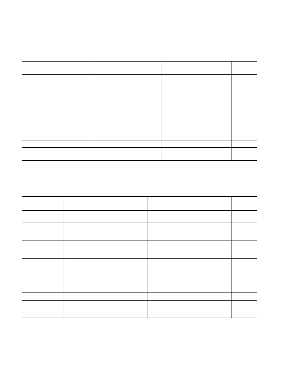
Table 1–5: Synchronization (Cont.)
Characteristic
Step
Number
Supplemental Information
Requirement
Remote sync
Amplitude
Sweep trigger polarity
2.0 to 5.0 V square wave, or 4.0 V
comp sync
Input and enabled through rear-panel
REMOTE connector. Input Impedance
1 M
W. 30/60 Hz (25/50 Hz) square
wave will sync 2FLD Sweep. Remote
sync bypasses the sync stripper and
field ID circuits.
Internal jumper selects polarity.
Normal: Negative-going edge line
sync, positive edge of field sync.
Inverted: Positive-going edge line
sync, negative edge of field sync.
90/100 Hz triggering amplitude
2.0 to 5.0 V square wave
90/100 Hz triggering frequency
NTSC: 90 Hz
±
15%
PAL: 100 Hz
±
15%
9
Table 1–6: RGB/YRGB Mode
Characteristic
Requirement
Supplemental Information
Step
Number
RGB/YRGB
Will display either a 3-step or 4-step RGB/
YRGB parade or overlay display.
Internal jumper is used to change from 3-step
to 4-step capability. Factory set to 3-step.
7
Staircase amplitude
A 10 V input will result in a horizontal display
of 9 divisions
±
1.4 major divisions.
Internal adjustment offsets any incoming
signal DC component between
±
12 V. Input
impedance 1 M
W shunted by approx. 3 pF.
7
Sweep repitition rate
Field or line rate of displayed video or external
sync signal as selected by front-panel
HORIZONTAL controls.
Field or line rate, if enabled from the REMOTE
connector.
7
Control
RGB/YRGB mode and parade/overlay
selected by applying ground (TTL low) at the
RGB enable pin on the rear-panel REMOTE
connector. RGB components may be
overlayed with normal sweep length by not
activating RGB enable.
Magnifier
Approx. X25 for 2FLD, and X10 in 1 or 2LINE.
Sweep length
3-step: 3.4 — 4.1 divs
4-step: 2.5 — 3.1 divs
Field or line rate sweeps. A 1FLD sweep is
selected by grounding the 1FLD/1LINE pin of
the rear-panel REMOTE connector.
7