Atec Tektronix-TDS5000B Series User Manual
Page 8
Digital Phosphor Oscilloscopes
•
www.tektronix.com/tds5000b
8
Digital Phosphor Oscilloscopes
TDS5000B Series
Trigger Modes
Edge – Positive or negative slope on any channel
or front panel auxiliary input. Coupling includes DC,
AC, noise reject, HF reject, and LF reject.
Video – Trigger on NTSC, PAL, SECAM, analog
HDTV, and non-standard video formats.
Glitch – Trigger on or reject glitches of positive,
negative or either polarity. Minimum glitch width
is 1.0 ns with 200 ps resolution.
Width – Trigger on width of positive or negative
pulse either within or out of selectable time limits
ranging from 1 ns to 1 s with 200 ps resolution.
Runt – Trigger on a pulse that crosses one thresh-
old but fails to cross a second threshold before
crossing the first again. Event can be time or logic
qualified (logic on 4 channel models only).
Window – Trigger on an event that enters or exits
a window defined by two user-adjustable thresh-
olds. Event can be time or logic qualified (logic
on 4 channel models only).
Timeout – Trigger on an event which remains
high, low or either, for a specified time period,
selectable from 1 ns to 1 s with 200 ps resolution.
Transition – Trigger on pulse edge rates that are
faster or slower than specified. Slope may be
positive, negative or either.
Setup/Hold – Trigger on violations of both setup
time and hold time between clock and data present
on any two input channels.
Pattern – Trigger when pattern goes false or stays
true for specified period of time. Pattern (AND, OR,
NAND, NOR) specified for four input channels
defined as High, Low or Don’t Care.
State – Any logical pattern of channels (1, 2, 3)
clocked by edge on channel 4 (channel 2 on
TDS5032B/5052B). Trigger on rising or falling
clock edge.
Comm (requires Opt. SM) – Support for AMI,
HDB3, B3ZS, B6ZS, B8ZS, CMI, NRZ and MLT3
encoded communication signals. Select among
isolated positive or negative one, zero pulse form
or eye patterns as applicable to standard.
Trigger Delay by Time – 16 ns to 250 seconds.
Trigger Delay by Events – 1 to
10,000,000 Events.
Waveform Measurements
Automatic Measurements – 53 of which 8 can be
displayed on screen at any one time.
Amplitude Related: Amplitude, High, Low, Maximum,
Minimum, Peak to Peak, Mean, Cycle Mean, RMS,
Cycle RMS, Positive Overshoot, Negative Overshoot.
Time Related: Rise Time, Fall Time, Positive Width,
Negative Width, Positive Duty Cycle, Negative Duty
Cycle, Period, Frequency, Delay.
Combination: Area, Cycle Area, Phase, Burst Width.
Histogram-related: Waveform count, Hits in box,
Peak hits, Median, Maximum, Minimum, Peak to
Peak, Mean (µ), Standard Deviation (σ), µ ± 1σ, µ ±
2σ, µ ± 3σ.
Communications Related: Extinction Ratio (abs, %,
dB), Eye Height, Eye Width, Eye Top, Eye Base,
Crossing %, Jitter (Pk-Pk, RMS, 6σ), Noise (Pk-Pk,
RMS), Signal/Noise Ratio, Cycle Distortion, Q-Factor.
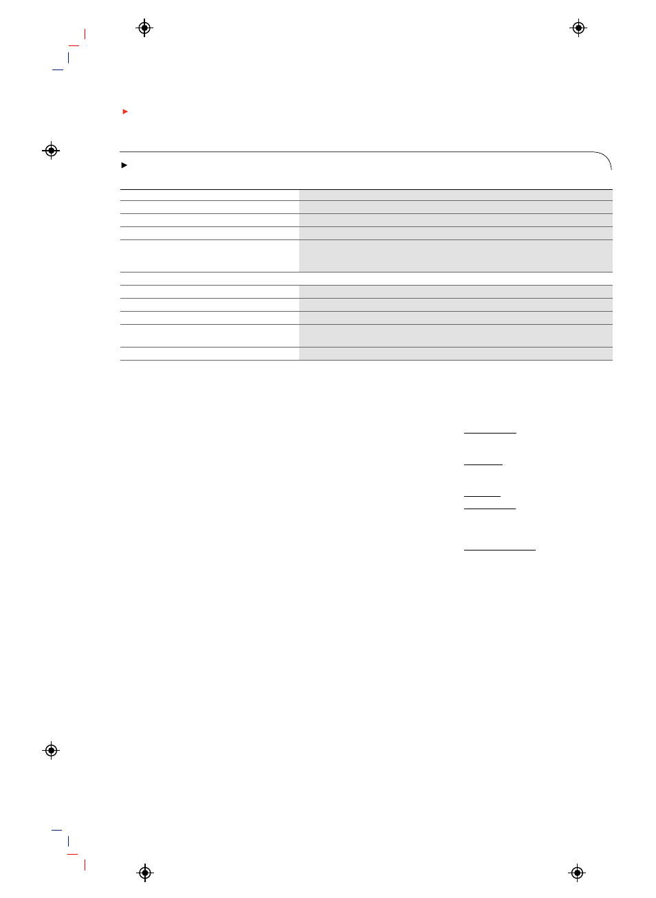
Tr i g g e r S y s t e m
All Models
Sensitivity
Internal DC Coupled
0.35 div DC to 50 MHz increasing to 1 div at rated bandwidth
External (auxiliary input)
400 mV from DC to 50 MHz increasing to 750 mV at 100 MHz
Main Trigger Modes
Auto, Normal, and Single
Trigger Sequences
Main, Delayed by time, Delayed by events. All sequences can include
separate horizontal delay after the trigger event to position
the acquisition window in time
Trigger Level Range
Any Channel
±10 divisions from center of screen
External (auxiliary in)
±8 V
Line
Fixed at 0 V
Trigger Coupling
DC, AC (attenuate <60 Hz), HF reject (attenuate >30 kHz)
LF reject (attenuates <80 kHz) Noise reject (reduce sensitivity)
Trigger Holdoff Range
1.5 µs to 12 s maximum