Atec Tektronix-TDS5000B Series User Manual
Page 5
Digital Phosphor Oscilloscopes
•
www.tektronix.com/tds5000b
5
Digital Phosphor Oscilloscopes
TDS5000B Series
capabilities of a Tektronix logic analyzer.
This integration allows designers to view
time-correlated digital and analog data in
the same display window and isolate the
analog characteristics of the digital signals
that are causing failures in their systems.
The iView Wizard simplifies this integration
of the oscilloscope and logic analyzer by
guiding the user through set up and con-
nection. No user calibration is required.
And, once set up, the iView feature is com-
pletely automated. The result – an integrated
tool set for digital design and troubleshooting.
Power Measurements
The TDS5000B Series’ powerful and flexible
measurements, math, and math-on-math
capabilities make it an ideal solution for
making power measurements, such as volt-
age, current, instantaneous power, and
energy for power device designers.
Communications Mask
Testing
Option SM provides a complete portfolio
of masks for verifying compliance to serial
communications standards. Masks are
provided for electrical standards up to
555 Mb/s and optical standards up to
1.25 Gb/s. Easily tailor mask testing to your
specific requirements using features such
as one-button mask autoset, autofit, user
adjustable mask margin tolerance, hit
counting, failure notifications, and built
in mask editing.
Video Design
Tektronix exclusive DPX acquisition technology
sets the TDS5000B Series apart from other
digital oscilloscopes, enabling the capture of
up to 100,000 waveforms per seconds for
a live, analog-like display. The TDS5000B
Series also supports a wide variety of video
standards with dedicated triggers including
NTSC, PAL, SECAM and analog HDTV. In
addition, IRE and mV graticules can be
selected for easier measurements and visual
inspection. All of this together makes the
TDS5000B Series an ideal tool for video
design and development.
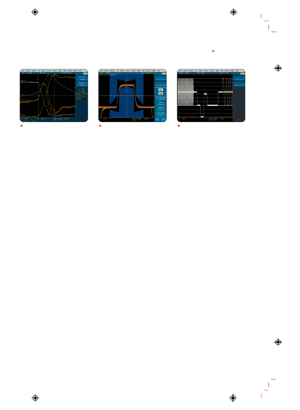
Power Measurements. Channel 1 (yellow,
labeled Voltage) shows the turn-off voltage
on the FET of a switching power supply,
with current on Channel 2 (blue, labeled
Current). The Math 1 waveform, M1 (orange,
labeled Power), is the instantaneous power
resulting from the multiplication of the volt-
age and current waveforms (Ch. 1 * Ch. 2).
The Math 2 waveform, M2 (purple, labeled
Energy), is the result of a calculation of the
integral of M1, a math-on-math operation
of the TDS5000B Series. An energy meas-
urement, located to the right of the display,
is a gated measurement made on M1 and
includes statistics.
Communication Mask Testing. Testing
an E1 signal against the mask specified
by the standard.
Video Design. Illustration of triggering on
an analog HDTV tri-level sync signal and
examining horizontal blanking interval.