Atec JDSU-JD748A-JD788A User Manual
Page 9
9
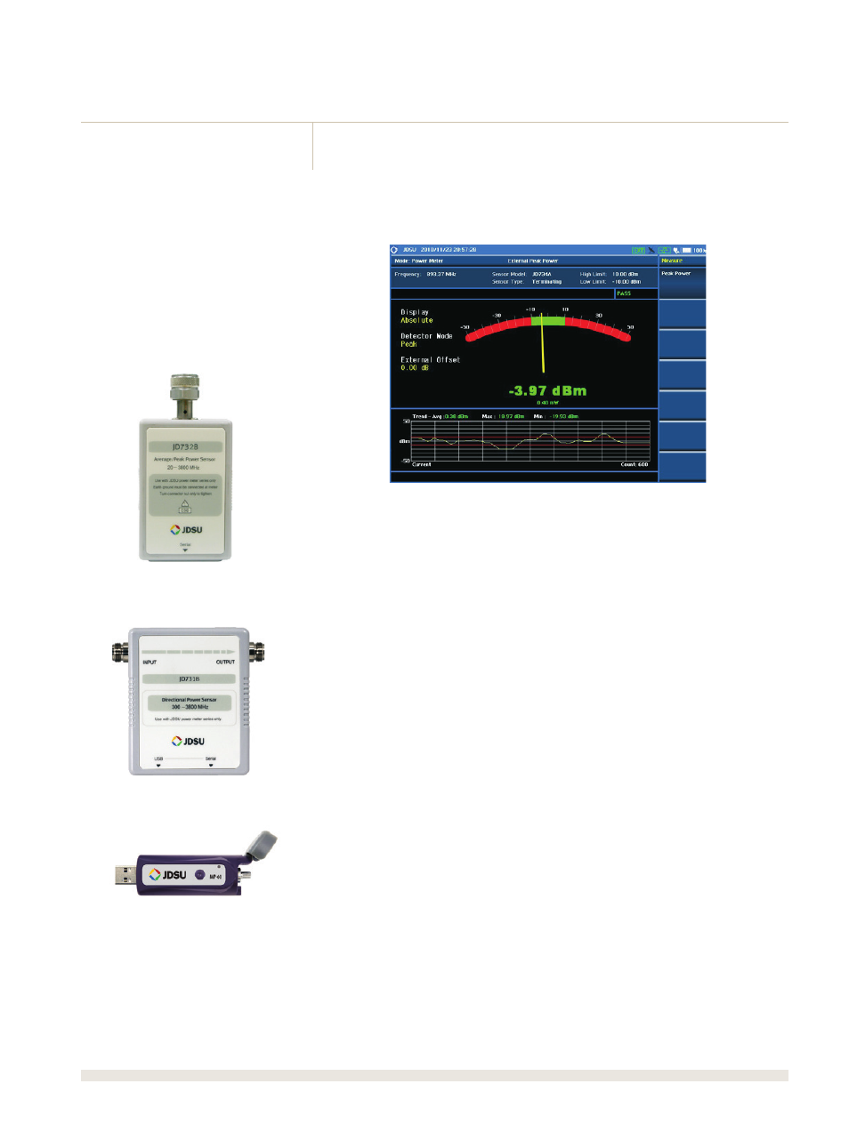
Th e power meter analysis has user-defi nable pass/fail limits and displays test results in
dBm and watts. Power measurements can be set as absolute measurements displayed
in dBm or as relative measurements displayed in dB.
Th e analyzer displays power levels in two formats, as a real-time value in an analog
meter and as a power-level trend through time in a histogram chart.
JD730-series high-precision RF power sensors measure RF power connected via USB
to the analyzer.
Th e analyzer controls terminating power sensors (JD732B, JD734B, and JD736B),
making it a highly accurate RF power meter for out-of-service applications up to
3.8 GHz with a measurement range of ‒30 to +20 dBm.
Th e analyzer controls directional power sensors (JD731B and JD733A) measuring
output power and impedance matching for in-service systems. Th ese power sensors
can handle up to 150 W of power, eliminating the need for attenuators.
Th e analyzer controls optical power sensors (MP-series) to measure optical power
quickly and easily in single-mode or multimode.
Th is optical power meter off ers a well-organized solution for fi ber inspection.
Terminating RF power sensor
Directional RF power sensor
Optical power sensor