Atec HP-Agilent-8110A User Manual
Page 5
5
Pattern Mode
Pattern length:
4 kbit/channel and
strobe output.
Output format:
RZ (return to zero),
NRZ (non-return to zero), DNRZ
(delayed non-return to zero).
Random pattern:
PRBS 2^(n-1) n = 7,8,...,12
Trigger Modes
Continuous:
continuous pulses,
double pulses, bursts (single or
double pulses) or patterns.
External triggered:
each active input
transition (rising, falling or both)
generates a single or double pulse,
burst or pattern.
External gated:
the active input level
(high or low) enables pulses, double
pulses, bursts or patterns. The last
single/double pulse, burst or pattern
is always
completed.
External width:
the pulse shape
can be recovered. Period and width of
an external input signal is main-
tained. Delay, levels and transitions
can be set.
Manual:
simulates an external input
signal.
Internal triggered (only with Agilent
81106A):
internal PLL replaces an
external trigger source. Pulses, double
pulses, bursts or patterns can be set.
Inputs and Outputs
External input
used for trigger, gate or external
width.
Input impedance:
50
Ω /10 kΩ selec-
table.
Threshold:
- 10 V to + 10 V.
Max. input voltage:
±
15 Vpp.
Sensitivity
::
≤ 300 mVpp typical.
Transitions:
< 100 ns.
Frequency:
dc to 150 MHz
Min. pulsewidth
:
3.3 ns
.
Strobe output and trigger output
Level:
TTL or ECL selectable.
Output impedance: 5
0
Ω typical.
Strobe output: user-defined, 16 kbit pat-
tern (NRZ) when in pattern mode.
Max. external voltage:
- 2 V/+7 V.
Transition times:
2 ns typical.
Pattern:
4096 bits NRZ in pattern
mode.
Delay from external input to strobe
output:
in pattern mode same as for
trigger output
.
Trigger Output
Level:
TTL or ECL selectable
Output impedance:
50
Ω typical
Trigger pulse width:
typically 50% of
period
Maximum external voltage:
-2 V/+7 V
Transition times:
2 ns typical
Delay from external input to trigger
output:
l8.5 ns typical
Agilent 81106A PLL/External Clock
for the Agilent 8110A
Can be retrofitted without
recalibration. Useful for
applications which require a phase
locked loop (PLL) or an external
clock:
Locking to an external frequency
reference:
the internal PLL is locked
to the 5 MHz or 10 MHz frequency at
the PLL reference input.
High accuracy:
the output period is
determined by the internal PLL.
Period accuracy, range, resolution,
and jitter are improved as shown in
the diagram. Asynchronous trigger-
ing possible
.
Internal triggered burst
:
the internal
PLL replaces an external trigger
source.
External clock:
the output period is
determined by signal at clock input.
Frequency accuracy can be increased
by using a precise external clock.
Trigger synchronously to external
clock:
the output period is
synchronous to the signal at clock
input. The signal at external input is
used for arming.
Period
Range:
6.65 ns to 999 s
Accuracy: ±0.1%
Resolution: 4 digits, 10ps best case
RMS-jitter: 0.003% + 20ps
Stability: 50 ppm/year typical
Trigger Modes
Standard trigger modes and:
Internal triggered:
pulses, double
pulses, bursts or patterns
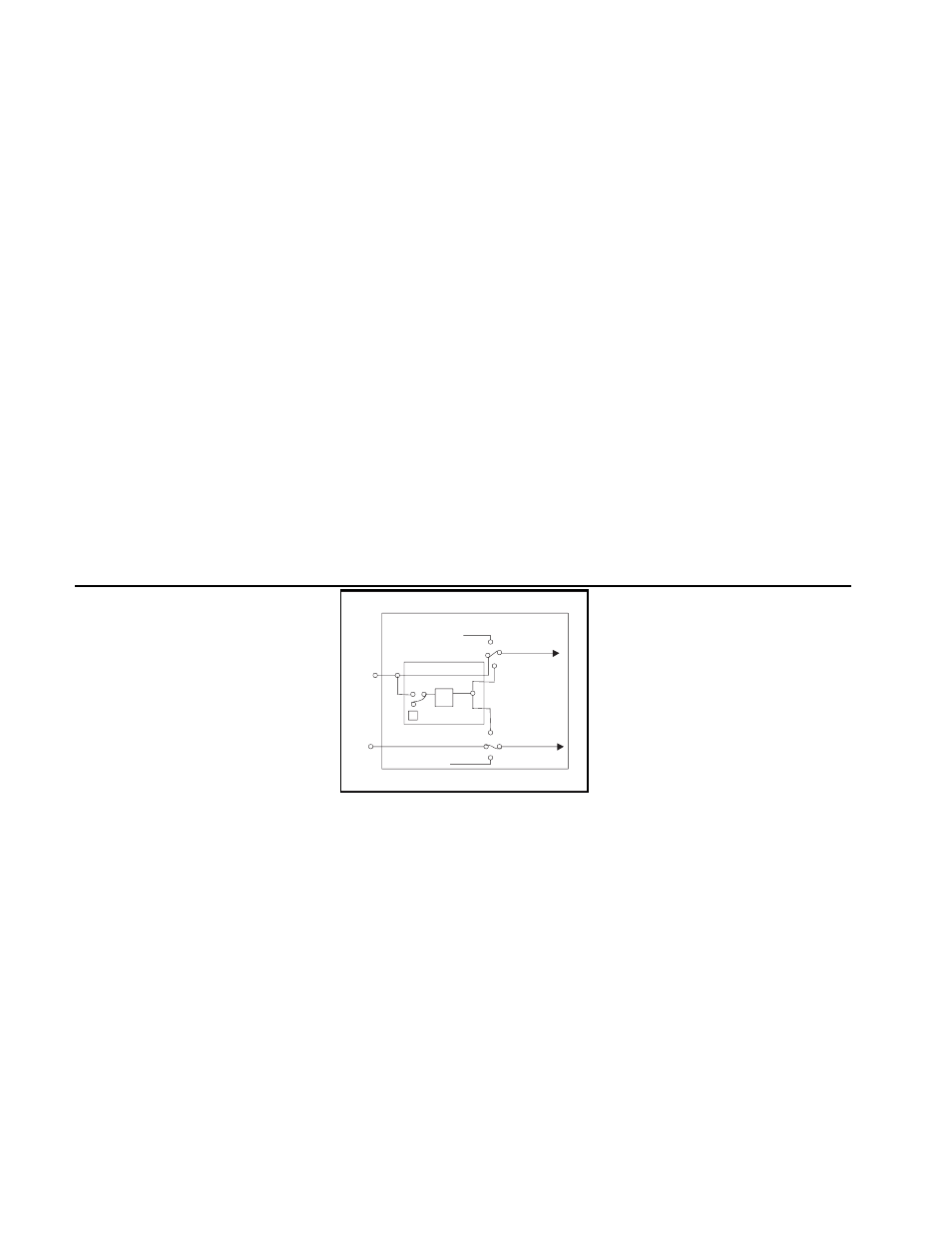
PLL
Agilent 81106A
Internal Oscillator
Agilent 8110A
Pulse Period
Trigger Signal
Continuous
External
Input
Clock
Input
PLL
Ref
Input
Figure 1
Clock Input/ PLL Reference Input to
be used as:
a) external system clock input pulse
frequency = input
frequency,
b) 5 MHz or 10 MHz frequency refer-
ence input for internal PLL.
Frequency can be measured. Rear
panel BNC connector.
Input impedance:
50
Ω or 10 kΩ
selectable
Threshold:
-10 V to +10 V
Maximum input voltage:
±15 V
Input transitions:<100 ns
Input Frequency
: dc to 150 MHz
Minimum Pulse width:
3.3 ns
Input sensitivity:
-300 mVpp typical
Delay from clock input to trigger
output:
22 ns typical