Atec Pacific-Power-118ACX User Manual
Page 2
i
j
k
l
m
n
o
j
p
l
q
p
l
r
p
s
s
o
t
l
u
v
w
w
x
y
z
{
|
}
~
x
w
v
j
p
l
q
p
l
s
o
p
o
t
r
j
p
l
q
p
l
q
j
o
s
k
j
m
s
o
n
p
k
m
l
j
t
15 to 200 Hz., 1%
200 to 800 Hz., 2%
800 to 1,200 Hz., 3%
j
p
l
q
p
l
l
j
s
l
j
t
15 to 200 Hz., < 0.25%
200 to 800 Hz., < 0.50%
800 to 1,200 Hz., < 1.00%
s
o
q
j
t
o
l
o
80 μSec. typical, 10–90% load step.
s
u
v
z
y
|
y
x
SCPI Commands, Baudrate up to 38.4 kBps
n
GPIB Interface, IEEE488.2 (replaces RS232)
Programmable Output Impedance Option
m
Harmonics, Analysis and Synthesis Option
Inrush Meter Option
p
q
r
l
w
v
z
y
|
y
}
w
x
License for Software UPC Test Manager
© 2011 Pacifi c Power Source, Inc. Subject to change without notice. #2ACXDS0811A
o
t
j
t
3.5"/88 mm x 16.75"/426 mm x 23.62"/600 mm (excluding
rack kit and TB cover)
o
n
l
40 lbs / 18.2 kg
r
j
j
k
t
n
Side intake with rear exhaust.
t
q
p
l
r
j
t
t
o
r
l
j
t
Compression terminals with strain relief. Optional power
cables available.
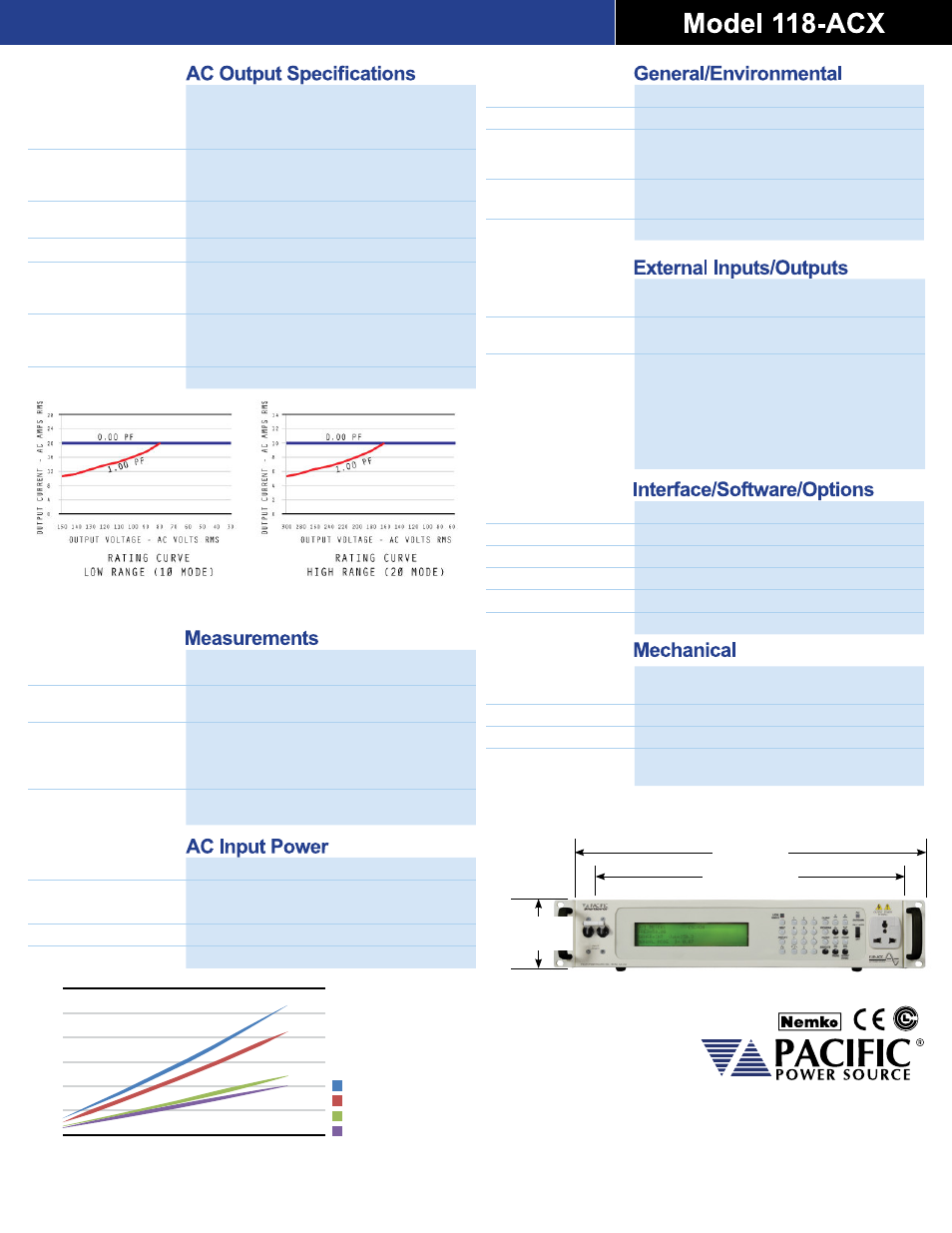
INPUT CURRENT
RATED POWER OUTPUT
100V
25.00
20.00
15.00
10.00
5.00
0.00
30.00
120%
100%
80%
60%
40%
20%
0%
120V
200V
240V
Input current versus Output Power
¡
¢
£
¤
¥
¦
§
¨
©
£
ª
«
¬
¨
®
¯
°
±
²
£
¨
«
¢
£
¥
¨
³
¨
²
´
¨
²
¨
£
¥
£
¨
£
«
k
µ
¶
s
y
|
}
w
{
}
·
s
y
|
}
w
20 A
RMS
30 A
RMS
40 A
PK
10 A
RMS
15 A
RMS
20 A
PK
s
y
|
}
w
s
w
v
µ
¸
z
{
µ
|
15 to 1,200 Hz
4 signifi cant digits
1800VA/1600W
Rated Max Peak
m
p
¹
t
q
p
l
External AC input algebraically summed with UPC waveform
and amplifi ed 35x to the direct coupled output.
m
t
q
p
l
±10% VDC input for each phase modulates the output
voltage ±100%.
t
r
j
p
l
q
p
l
TTL signals are provided to synchronize external test
equipment to the power source output.
1. TTL pulse at Zero Crossing, Phase A
2. Transient Pedestal – TTL signal, True for duration of
Transient Event.
3. DRM – TTL Clock – multiple of output frequency.
j
q
o
s
m
l
t
n
l
o
q
º
Full Power 0-40ºC; Reduced Power 40º-55ºC
s
o
k
m
l
i
o
p
l
0-95% (non condensing)
r
p
s
s
o
t
l
k
l
r
p
s
s
o
t
l
q
s
j
l
o
r
l
m
i
o
j
s
k
»
s
m
s
22 executable waveforms in Non-Volatile RAM.
¼
½
¾
¿
А
Б
В
Г
Д
Е
Ж
З
И
Й
В
К
Л
Ж
М
Н
¿
А
¾
¼
О
П
Р
Н
С
Е
Т
К
Л
У
Ф
¼
¿
О
¿
Х
А
Ц
¼
Х
¼
Ч
Ш
Ш
Б
Щ
Ъ
У
Ф
¼
¿
О
¿
Х
½
Ц
¾
Х
Ш
½
Ц
¾
Ы
Т
Ь
Ь
Б
И
Л
Л
У
Ч
Ш
Ш
Х
Ч
Ц
О
Х
А
О
Э
Э
Ю
Я
а
Щ
В
Ь
У
б
Щ
Ь
Л
б
в
г
Щ
Д
В
д
Д
г
Т
е
Л
И
Х
Д
Т
а
е
е
е
Х
г
Щ
Д
В
д
Д
г
Т
е
Л
И
Х
Д
Т
а
s
y
|
}
w
s
w
v
µ
¸
z
{
µ
|
m
~
~
x
y
~
æ
s
y
|
}
w
s
w
v
µ
¸
z
{
µ
|
m
~
~
x
y
~
æ
s
y
|
}
w
w
¸
y
æ
0 to 50 A
PK
0.025 I
PK
±3% of full scale
0-150/0-300 Vac
0.1 Vac steps
±0.05% of command voltage referenced to the
internal voltmeter with CSC engaged.
0.1-124.0 A
RMS
0.1 to 655.35 Sec.
i
j
k
l
m
n
o
u
l
x
w
s
r
p
s
s
o
t
l
u
l
x
w
s
q
j
o
s
q
j
o
s
r
s
o
l
m
r
l
j
s
Calculated and displayed to three signifi cant digits.
s
y
|
}
w
m
~
~
x
y
~
æ
s
y
|
}
w
m
~
~
x
y
~
æ
0-354 VLN, 708 VLL
±0.2% of range +cal.ref.
50 A
PK
±0.2% of range +cal.ref.
True Power, Apparent Power and calculates
Power Factor.
10,680 W
1.0 Watts or VA
w
y
v
x
w
v
s
y
|
}
w
s
w
v
µ
¸
z
{
µ
|
з
®
®
и
й
к
л
£
²
м
°
й
н
¥
£
©
£
³
о
«
©
£
¨
²
´
£
²
¥
£
«
к
¨
³
о
£
£
¨
¨
£
£
²
³
´
¨
«
19"/ 483 mm
16.75"/ 426 mm
3.5"/ 88 mm
(2U)
п
р
с
т
т
у
ф
х
ц
ч
ш
щ
ъ
ы
щ
ш
ь
э
ы
ъ
ю
я
¡
ы
э
¢
£
¤
я
¥
я
¦
§
¨
ы
©
ш
¥
ы
э
¤
¢
я
¥
ы
¤
ш
я
э
£
я
э
ш
¤
£
¥
я
ш
ъ
ы
ъ
¢
я
э
¤
£
э
ъ
ы
щ
US
t
q
p
l
i
j
k
l
m
n
o
1 Phase, 100–240 VAC ± 10%
t
q
p
l
r
p
s
s
o
t
l
u
v
w
w
~
·
y
x
z
t
q
p
l
s
o
p
o
t
r
47–63 Hz
t
q
p
l
q
>0.98
Full Rated Load: 22 A
RMS
at 120V, 11 A
RMS
at 240V