Accuracy, resolution and range – Atec Fluke-430 Series User Manual
Page 8
8 Fluke Corporation Fluke 430 Series Three-Phase Power Quality Analyzers
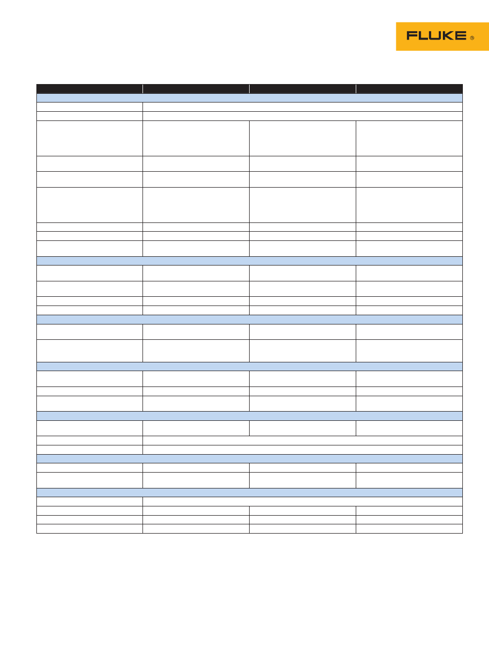
Measurement range
Resolution
Accuracy
Harmonics
Harmonic order (n)
DC, 1 to 50 grouping: harmonic groups according to IEC 61000-4-7
Inter-Harmonic order
Off, 1 to 49 grouping: harmonic and interharmonic subgroups according to IEC 61000-4-7
Vrms
Relative (%f):
Fluke 435 Absolute:
Fluke 434 Absolute:
0.0 % to 100.0 %
0.0 Vrms to 1000 Vrms
0.0 Vrms to 1000 Vrms
0.1 %
0.1 Vrms
0.1 Vrms
± 0.1 % ± n x 0.1 % (± 0.4 % for %r)
± 0.05 % of nominal voltage if
< 1 % of nominal voltage
± 5 % if
≥ 1 % of nominal voltage
± 5 % ± 2 counts
Arms
Relative (%f):
Absolute:
0.0 % to 100.0 %
0.0 mV to 4000 mV x clamp scaling
0.1 %
1 mVrms x clamp scaling
± 0.1 % ± n x 0.1 % (± 0.4 % for %r)
± 5 % ± 5 counts
Watts
Relative:
(Harmonics only)
Absolute:
0.0 % to 100.0 %
depends on clamp and voltage scaling
0.1 %
± n x 2 %
± 5 % ± n x 2 % ± 10 counts
DC
Relative:
Fluke 435 Absolute V:
Fluke 434 Absolute V:
Absolute A:
Absolute W:
0.0 % to 100.0 %
0.0 V to 1000 V
0.0 V to 1000 V
0.0 mV to 4000 mV x clamp scaling
depends on clamp and voltage scaling
0.1 %
0.1 V
0.1 V
1 mVrms x clamp scaling 0.1 V
depends on scaling
± 0.1 % V and A (± 2 % Watt)
± 0.2 % of nominal voltage
± 5 % ± 10 counts
± 5 % ± 10 counts
± 5 % ± 10 counts
THD
(n=40)
(relative %f or %r) 0.0 % to 100.0 %
0.1 %
± 2.5 % V and A (± 5 % Watt)
Hz
0 Hz to 3500 Hz
1 Hz
± 1 Hz
Phase angle
Fluke 435
Fluke 434
-360 º to +0 º
-360 º to +0 º
1 º
1 º
± n × 1 º (
8
)
± n × 1.5 º (
8
)
Power and energy
Watt (VA, VAR)
Fluke 435
Fluke 434
1.0 MW to 20.00 MW
1
1.0 MW to 20.00 MW
1
0.1 kW to 1 kW
1
0.1 kW to 1 kW
1
± 1 % ± 10 counts
3
± 1.5 % ± 10 counts
3
kWh
6
(kVA
6
, kVAR
6
)
00.00 kWhr to 200.0 GWhr
1
00.00 kWhr to 200.0 GWhr
1
0.01 Xhr to 100 Whr
1
0.01 Whr to 100 Whr
1
± 1 % ± 10 counts
3
± 1.5 % ± 10 counts
3
Power Factor
0 to 1
0.01
± 0.033
Cos
j/DPF
0 to 1
0.01
± 0.033
Flicker
Pst (1min), Pst, Plt, PF5 instantenous
Flicker
0.00 to 20.00
0.01
Within ± 5 % of tabulated values
according IEC61000-4-15
Dc%, Dmax% and Time d(t)
exceeds limits as described per
IEC 61000-3-3
0.0 % to ± 100.0 % for Dc% and
Dmax% and 0.000 s to 9.999s for
Time
0.1 % for Dc% and Dmax% and 10 ms
for Time
± 1 % for Dc% and Dmax% and 20 ms
for Time
Unbalance
Volts Fluke 435 (neg. and zero seq.)
Fluke 434 (neg. and zero seq.)
0.0 % to 5.0 %
0.0 % to 5.0 %
0.1 %
0.1 %
± 0.15 %
± 0.5 %
Current
(neg. and zero seq.) 0.0 % to 20 %
0.1 %
± 1 %
Phase angle
volts
current
-360.0 ° to 0.0 °
-360.0 ° to 0.0 °
0.1 º
0.1 º
± 2 counts
± 5 counts
3
Transient capture
Volts
cursor reading
rms reading
± 6000 Vpk
10 Vrms to 1000 Vrms
1 V
1 V
± 15 % of cursor reading
± 2.5 % of Vnominal
Minimum detect duration
5 µs
Sampling rate
200 kS/s
Inrush mode
Arms (ac+dc)
0.000 kArms to 20.00 kArms
1
0.001 Arms to 10 Arms
1
± 1 % of meas ± 5 counts
Inrush Duration
mm:ss:mmm between 7.5 s to
30 minutes selectable
10 ms
± 20 ms (Fnominal = 50 Hz)
Mains Signaling
4
Threshold levels
Thresholds, limits and signaling duration is programable for two independent signaling frequencies
Signaling frequency
60 Hz to 3000 Hz
0.1 Hz
Relative V%
0 % to 100 % of Vnominal
0.1 %
± 0.4 %
Absolute V3s (3 second average)
0.0 V to 1000 V
0.1 V
± 5 % of nominal voltage
Accuracy, resolution and range
cont.