General specifications, Wiring configurations, Measurement method – Atec Fluke-430 Series User Manual
Page 10
10 Fluke Corporation Fluke 430 Series Three-Phase Power Quality Analyzers
VA
Selectable total or fundamental apparent power display
Calculates apparent power using Vrms x Arms value over 10/12 cycle period
Total apparent power is root mean square of real and reactive power
VAR
Selectable total of fundamental reactive power display
Calculates reactive power as root of VA squared minus watt squared over 10/12 cycle period
Capacitive and inductive load is indicated with capacitor and inductor icons
Power Factor
Calculated watt/VA
Cos
j/DPF
Cos of angle between fundamental voltage and current
Unbalance
The supply voltage unbalance is evaluated using the method of symmetrical components according to
IEC61000-4-30
Flicker
According to IEC 61000-4-15 flickermeter—functional and design specification
Includes 230 V 50 Hz lamp and 120 V 60 Hz lamp models
Transient capture
Captures waveform triggered on signal envelope
Additionally triggers on dips, swells, interruptions and Amps level as specified by IEC61000-4-30
Inrush current
The inrush current begins when the Arms half cycle rises above the inrush threshold, and ends when the Arms half
cycle rms is equal to or below the inrush threshold minus a user-selected hysteresis value. The measurement is the
square root of the mean of the squared Arms half cycle values measured during the inrush duration. Each half-cycle
interval is contiguous and non-overlapping as recommended by IEC 61000-4-30. Markers indicate inrush duration.
Cursors allow measurement of peak Arms half cycle.
Mains signaling
Measurements are based on: either the corresponding 10/12-cycle rms value interharmonic bin or the rms of the
four nearest 10/12-cycle rms value interharmonic bins per IEC 61000-4-30
Limit setup for Monitor mode follows EN50160 “Meistercurve”
Time synchronization
Optional GPS430 timesync module provides time uncertainty
≤ 20 ms or ≤ 16.7 ms
2
for time tagging of events and
time aggregated measurements. When synchoronisation becomes unavailable, time tolerance is
≤ 1-s/24h
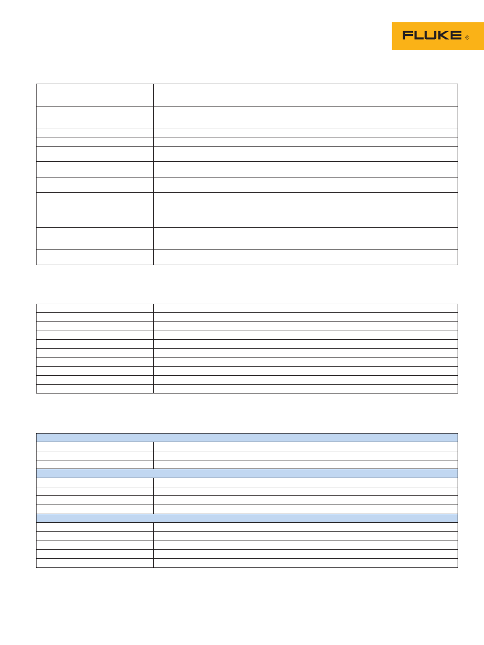
Wiring configurations
1Ø + NEUTRAL
Single phase with neutral
1Ø SPLIT PHASE
Split phase
1Ø IT NO NEUTRAL
Single phase system with two phase voltages without neutral
3Ø WYE
Three phase four wire system WYE
3Ø DELTA
Three phase three wire system Delta
3Ø IT
Three phase system without neutral WYE
3Ø HIGH LEG
Four wire three phase Delta system with center tapped high leg
3Ø OPEN LEG
Open delta three wire system with 2 transformer windings
2-ELEMENT
Three phase three wire system without current sensor on phase L2/B (2 watt meter method)
2½-ELEMENT
Three phase four wire system without voltage sensor on phase L2/B
Measurement method
cont.
General specifications
Case
Design
Rugged, shock proof with integrated protective holster
Drip and dust proof
IP51 according to IEC60529 when used in tilt stand position
Shock and vibration
Shock 30 g, vibration: 3 g sinusoid, random 0.03 g
2
/Hz according to MIL-PRF-28800F Class 2
Display
Type
Bright full-color LCD with CCFL backlight, 80 cd/m
2
Size
115.2 mm x 86.4 mm (4.5 in x 3.4 in)
Resolution
320 x 240 pixels
Contrast and brightness
User-adjustable, temperature compensated
Memory
Screens
50 screen memories
Data
10 data memories for storing data including recordings
Logger
User configurable shared memory, up to 15 MB on Fluke 435, Up to 7 MB on Fluke 434
4
Limit templates
2 preprogrammed, 2 administrator (programmable via FlukeView
®
), 2 user locations
Real-time clock
Time and date stamp for AutoTrend, Transient display and SystemMonitor