Specifications, Vds-2002 voltage dip and up simulator – Atec Noiseken-VDS-2002 User Manual
Page 4
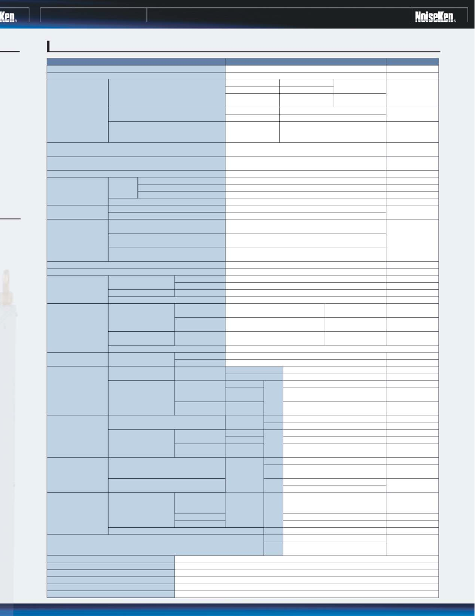
VDS-2002
Voltage Dip and Up Simulator
IEC 61000-4-11
Single phase
Synchronous
Short circuit
Open circuit
PC/Local
Only 2s-1s-2s standard defined test
available in local mode
PC/local
PC
PC/local
PC
PC
Asynchronous
Synchronous
Asynchronous
Asynchronous
Synchronous/Asyn
chronous
Parameters
Compliant standard
Number of lines
AC90~264V, 50/60 Hz
DC0~125V
AC0V~120% of input voltage
DC0V~input voltage
4.224kVA
Input voltage range
Output voltage range
Output VA
Output current
capability
Dip and swell
Variation
AC
DC
Peak inrush current
drive capability
AC100~120V
16A rms
23A rms
40A rms
Continuous
Continuous
Continuous
5S
5S
16A
250A
500A
5%
7%
10%
5%
1~5
ȐS
~120%
100%
10V~290V
0V~16A output
ȗ5V
ȗ5V
1~1000 or continuous
1, 3, 5, 10, 30, 50, 100 or continuous
PC
Local
Synchronous
Synchronous
Synchronous
Synchronous
Asynchronous
Asynchronous
Asynchronous
Asynchronous
Synchronous
Asynchronous
PC
PC
PC
PC
PC
PC
PC
PC
PC
0~359
f
0, 45, 90, 135, 180, 225, 270, 315
0~19.9 ms for 50Hz
0~10s
0~100s
0.1s step
0.1s step
Test sequence stored
up to 10 steps when
controlled by PC
0~16.6 ms for 60Hz
0~120%
AC100~115V/200~240V
ȗ10%, 50/60Hz, 120VA
5 tests
10 steps
0.1s~10 s
at least 0.1s required for 10% change
of input
1~100s
1s~10h
0.01~5000 cycles
0.5, 1, 5, 10, 25, 50 cycles
0.1 ms~100s
10ms~100s (50Hz)
8.3ms~100s (60Hz)
PC
Local
Local
Local
Local
PC
PC
Local
PC
Setting by percent
100% of input voltage
0~40A rms
70% of input voltage
0~23A rms
100% of input voltage
0~16A rms
Setting by voltage
Accuracy
Setting by percent
Setting by voltage
Accuracy
No. of events
Setting by cycle
Setting by time
Setting by time
Setting by time
Setting by phase angle
Setting by time
Setting by cycle
Setting for short
duration
Setting for long
duration
Setting for short
duration
Setting for long
duration
Changing time
Changed time
Interval
Test level
Equipment input
optical RS-232
External interface
15~35
fC
Operating temperature
25~75%R.H. (No dewing)
Operating humidity
(W)430
҂(H)745҂(D)600mm(projection excluded)
Dimensions
Approx.150 kgs.
Weight
Interval cycle
Dip cycle
Dip phase
(Starting phase angle of
events)
Voltage variation test
Memory
Repetition of events
Normal voltage setting
Dip/Swell level
Rise time/fall time
Overshoot/undershoot
Load regulation
Local
0.5~5000.5 cycles
10 steps
1s step
1s step
1s step
0.1s step
0.1ms step
1
f step
8 steps
(45 degrees step)
0.1 ms step
0.01 cycle step
6 steps
0.1ms step
0.1 ms~100s
1s~10h
0.1ms step
0.5 cycle step
8 steps
1 event step
5V step
4 steps
5V step
10V minimum
100 ohm loaded
100 ohm loaded
AC290V max
at 100% output,
10ms
1,3,5,10,30,50,100,300,500 cycles, 10s
0~120%
Short/Open selectable for 0%
(interruption)
0/40/70/120%
Short circuit for 0%
(interruption) setting
0~290V (0~120%)
Short/Open selectable for 0V
(interruption)
AC220~240V
100% of input voltage
70% of input voltage
40% of input voltage
Interruption
AC/DC
Test mode
Specifications
Remarks
SPECIFICATIONS