Electrical schematic operating principle – Atec Noiseken-VDS-2002 User Manual
Page 3
VDS-2002
Voltage Dip and Up Simulator
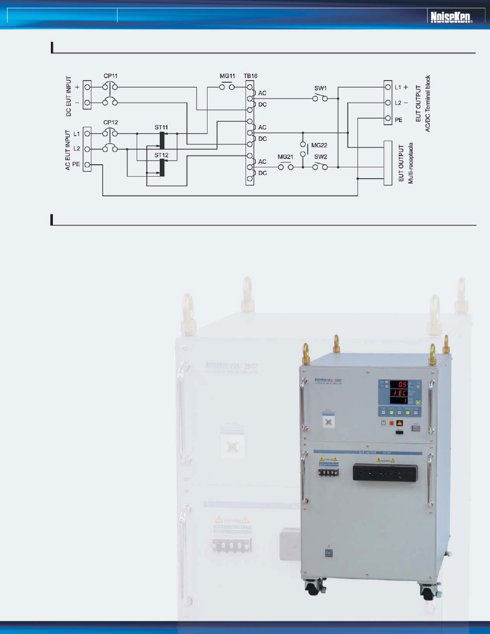
As shown in the above schematic, the VDS employs two
independent motor-driven slide transformers and two IGBT
switches. Under complete control by the unit control circuitry, it
generates voltages dips, interruptions and variations with much
wider parameter settings than those originally required in the IEC
61000-4-11 standard.
Since the unit employs two slide transformers, it can generate
two variable voltage levels, which are independently preset,
corresponding to dip (or variation) and normal voltage (voltage in
interval cycles). The two IGBT switches enable to fulfill the fast
rise and fall time requirements called for in the relevant standard.
AC/DC selection terminals are provided to insert the two
transformers for an AC test and to bypass them for the DC test.
DC interruption test, therefore, can be done by utilizing the same
IGBT switches.
To offer short and open mode selection in AC interruption test,
two magnet relays, MG22 and MG21, work to realize low
impedance and high impedance as seen from the load side.
ELECTRICAL SCHEMATIC
OPERATING PRINCIPLE