Atec Fluke-910-910R User Manual
Page 2
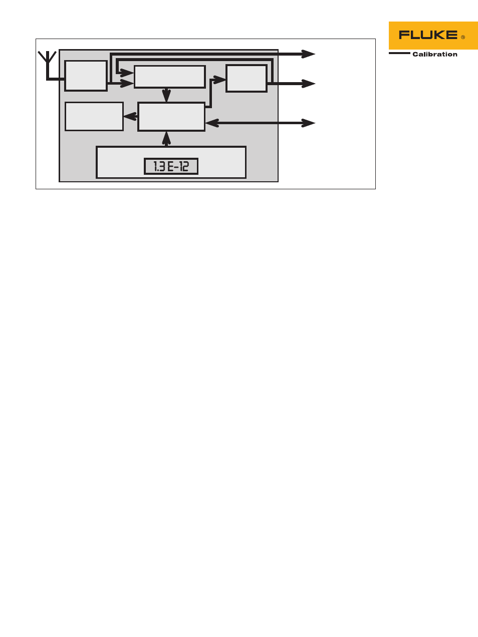
Figure 2. The Fluke Calibration 910 and 910R have built-in comparison between the GPS receiver and the internal oscillator. The frequency
offset is displayed and stored and a traceability record can be produced at any time.
Up to 13 outputs, maximizing
cost efficiency
Both models come with one 5 MHz
and five 10 MHz sinewave
outputs as standard. A one
pulse-per-second output is also
included.
If your application requires
more outputs—for example, if
several other instruments need
to be supplied from the same
frequency standard—option 70
allows you to mount five more
10 MHz outputs. Alternatively,
option 72 allows you to expand
your instrument to give five
extra 2.048 MHz outputs, which
is particularly useful in many
telecoms applications. Option
73 provides five extra 13 MHz
outputs, the standard frequency
for GSM base station master
clocks. Another variant on output
configuration is offered through
option 71, which gives the
instrument an additional four
sine wave outputs of 10 MHz,
5 MHz, 1 MHz and 0.1 Hz, plus a
0.1 MHz square wave output.
And finally, option 75 allows
you to define your own pulse
frequency output.
Central or remote monitoring,
management and data col-
lection, using the 910/910R
Ethernet-port
The 910 and 910R can both be
fitted with an optional Ethernet
communication interface (option
76) which enables on-line
access. Using the GPSView
TM
software supplied, it is possible
to monitor both instrument and
GPS status, or even collect cali-
bration data, via the internet or
any Local Area Network.
With Ethernet interface con-
nectivity, distances to which
data can be transmitted become
unlimited, unlike that of any
standard GPIB or RS-232 inter-
terface, thereby allowing the
910/910R to be monitored from
practically anywhere.
This means that the metro-
logist or lab technician no
longer requires a ‘floating’
laptop PC to directly perform
instrument management tasks,
as this can now be achieved
from any desktop PC, from
any location inside or outside
the calibration laboratory. It
also allows data from multiple
instruments to be simultane-
ously viewed in real time.
Two high-stability operating
modes to suit your application
Most users prefer automatic
adjustment (known as disciplin-
ing) of their frequency standard,
to fully eliminate long-term
frequency changes (aging).
This disciplined mode is also
the default mode in the 910
and 910R. As long as there is a
valid satellite signal, the internal
local oscillator is monitored and
adjusted and the mean 24-hour
frequency offset is always
virtually zero. However, in this
mode, the inherent short-to-
medium term stability of all local
oscillators, except rubidium, is
compromised. This is true for all
GPS frequency references. The
received GPS signal has rela-
tively large short-term frequency
variations, due to variations in
atmospheric conditions. This
means that when using the
received GPS signal for disciplin-
ing the 910 (OXCO), the stability
is reduced a little for averaging
times of 100 s to 1000 s.
In this mode, the frequency
deviation between the inter-
nal timebase oscillator and the
received GPS-signal is used to
continuously adjust the oscillator
(disciplining). The resulting fre-
quency offset and adjustment data
is stored in non-volatile memory
every 24-hours, to enable print-
out of the traceability record. The
actual frequency offset (24h mean
value) is calculated and displayed
on the front panel.
Some applications demand
superior short-medium term
stability, especially for jitter and
wander measurements in digital
telecommunication networks.
The unique manual hold-over
mode makes it possible to switch
over temporarily from disciplined
to hold-over mode during the
actual measurement, thereby
achieving a superior frequency
accuracy at the start of the mea-
surement and a superior stability
through the measurement.
Here, the internal oscilla-
tor is not adjusted. This mode is
normally automatically entered
when there is no usable received
GPS-signal. This mode can also
GPS-
Receiver
High resolution
counter
Measurement
storage
(Calibration data)
Microprocessor
Rubidium
or OCXO
oscillator
Front panel display of frequency offset
1 pps Out
Reference Out (10 MHz)
To PC (RS232)
1pps
Optional Ethernet
interface
2 Fluke Calibration 910/910R GPS Controlled Frequency Standards